Engine Electrical Devices: 1C-17
Trim Sensor Inspection
Z9J0111306018
1) Turn ignition switch OFF.
2) Connect 3-pin test cord between trim sensor and
wire harness as shown in figure.
3) Turn the ignition switch ON.
4) Connect tester probe as shown in the illustration and
check for sensor power source voltage.
Sensor power source voltage
Standard: Approx. 5 V
Special tool
(A): 09930–89220 (3-pin connector test
cord)
(B): 09930–99320 (Digital tester)
Tester knob indication
DC Voltage
Power source voltage
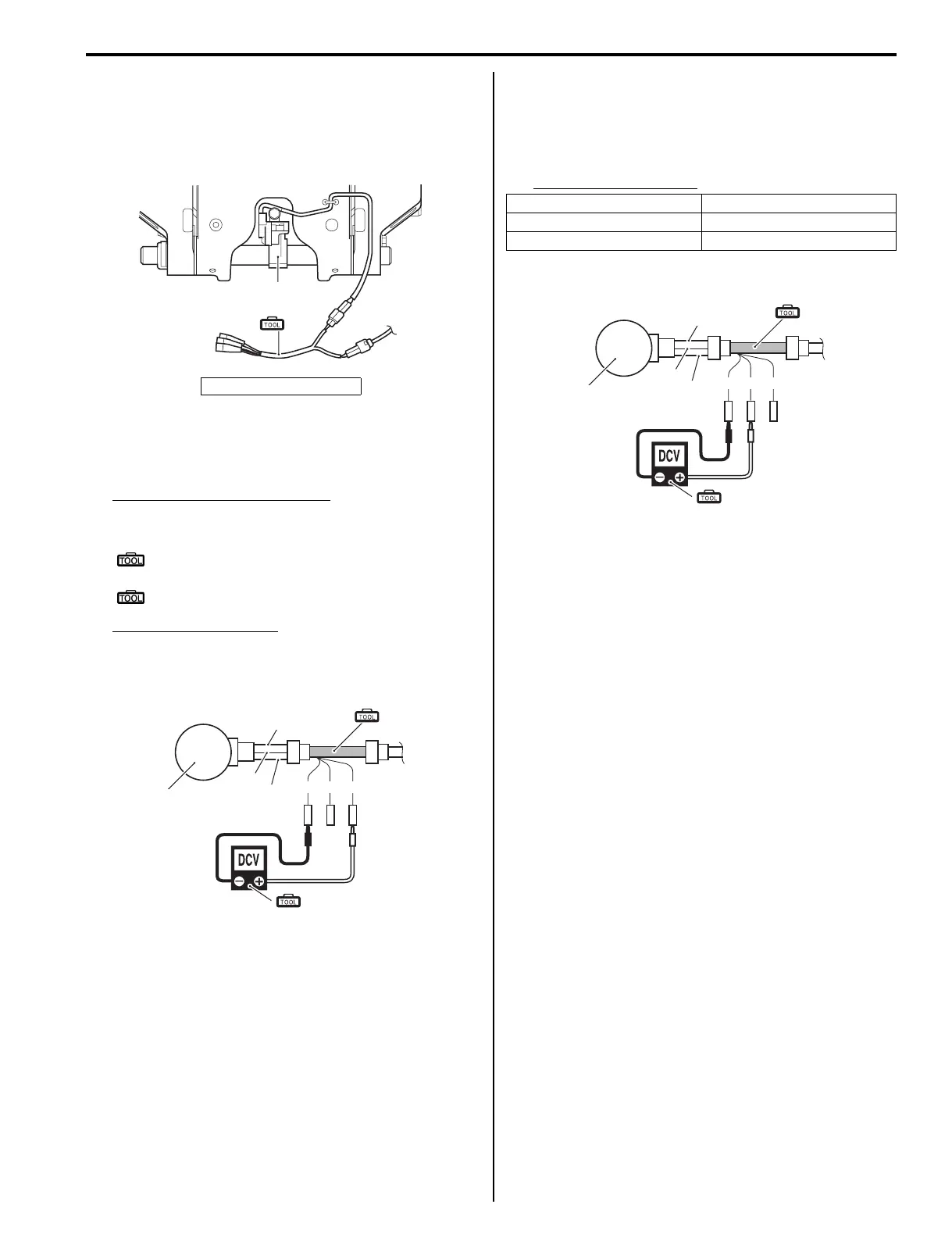
5) Connect tester probe as shown in the illustration.
Check for sensor output voltage.
Operate the PTT switch, and check if voltage
changes linearly within specification, according to
trim/tilt position.
Sensor output voltage
Output voltage
6) If out of specification, check wire harnesses for open
and short. If wire harnesses are in good condition,
replace trim sensor and recheck.
1. Trim sensor
1
(A)
I9J011130050-03
Bl
Y
B
W R B/W
1
(A)
(B)
I9J011130024-03
Trim/Tilt position Output voltage
Full trim down Approx. 0.9 V
Full tilt up Approx. 4.0 V
Bl
Y
B
W R B/W
1
(A)
(B)
I9J011130025-03