1A-34 Engine General Information and Diagnosis:
Self-Diagnostic Code “3 – 3” Neutral Switch
Z9J0111104014
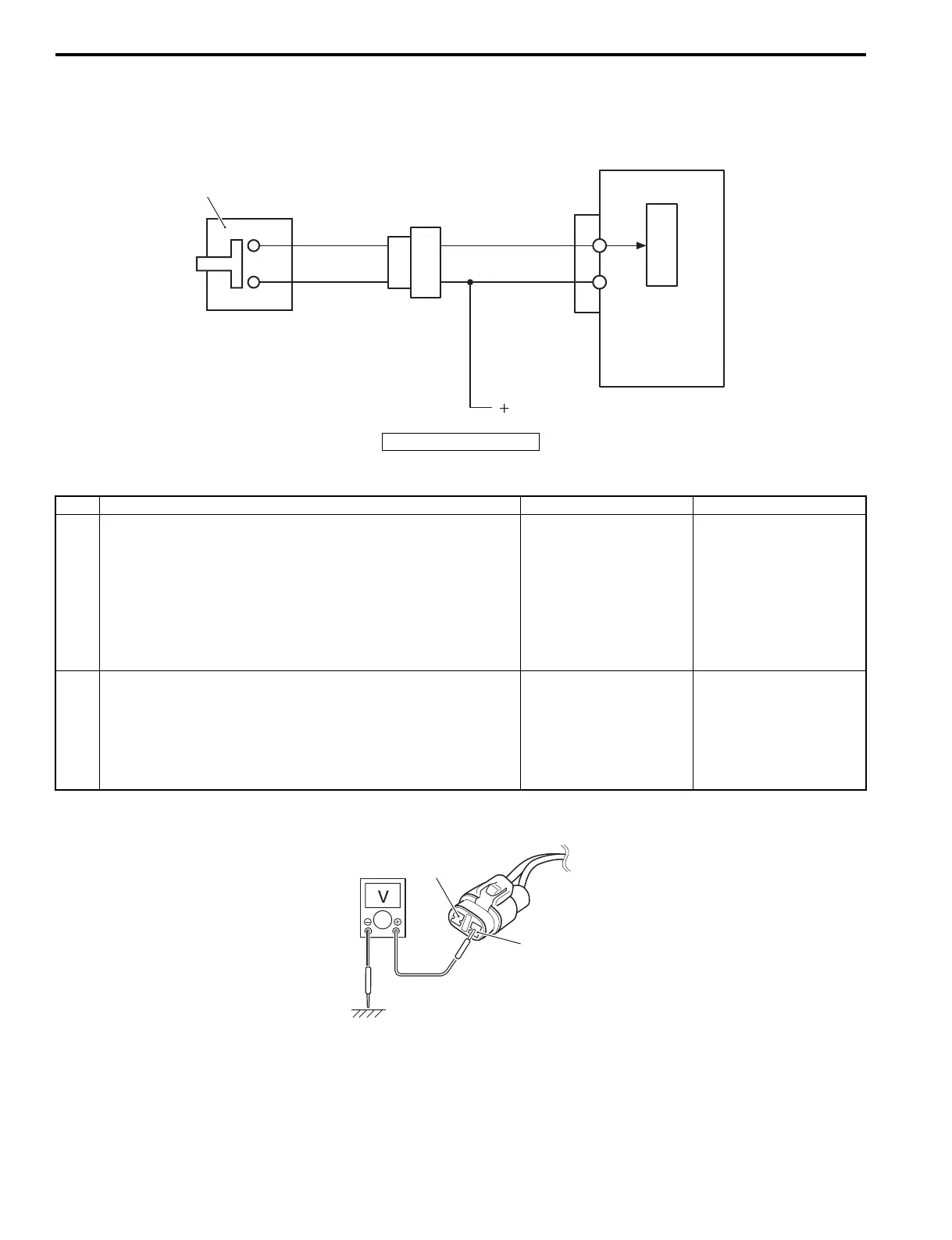
Wiring Diagram
Troubleshooting
For step 1
ECM
Y/G
B/Bl
Y/G
Br
C
P
U
1
12V (From Ign. switch)
I9J011110033-04
1. Neutral switch
Step Action Yes No
1 1) With the ignition switch “OFF”, disconnect the neutral
switch connector.
2) With the ignition switch “ON”, check the voltage at the
“B/Bl” wire terminal of the neutral switch connector.
Is the voltage 12 V or more?
Go to step 2. • “B/Bl” wire shorted to
“Y/G” wire or ground
circuit.
• If the wiring and
connection is OK,
substitute a known-
good ECM and
recheck.
2 1) Check the Neutral Switch.
Refer to “Neutral Switch Inspection” in Section 1I
(Page 1I-14).
Is it in good condition?
• Poor neutral switch
connection,
intermittent trouble or
a faulty ECM.
• Shift position sensor
lever damage.
Faulty neutral switch.
Y/G
B/Bl
I9J011110051-02