1C-16 Engine Electrical Devices:
Shift Position Sensor Inspection
Z9J0111306017
1) Turn ignition switch OFF.
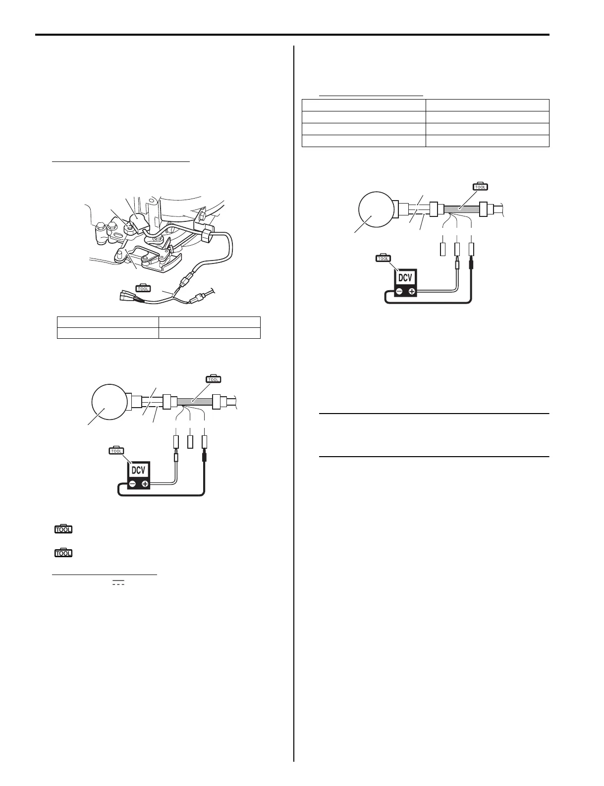
2) Connect 3-pin test cord between shift position
sensor and wire harness as shown in figure.
3) Turn the ignition switch ON.
4) Connect tester probe as shown in the illustration and
check for sensor power source voltage.
Sensor power source voltage
Standard: Approx. 5 V
Power source voltage
Special tool
(A): 09930–89220 (3-pin connector test
cord)
(B): 09930–99320 (Digital tester)
Tester knob indication
DC Voltage ( )
5) Connect tester probe as shown in the illustration.
Check for sensor output voltage while operating
remo-con handle.
Sensor output voltage
Output voltage
If out of specification:
• 1st; Check remo-con cable adjustment, readjust if
necessary.
• 2nd; Check wire harnesses for open and short.
If wire harnesses are in good condition, replace
shift position sensor and recheck.
NOTE
After installing shift position sensor, check
for proper correct function by operating
remo-con handle.
1. Shift position sensor 3. Clutch lever
2. Adjust screw
(A)
3
1
2
I9J011130023-02
Bl
Y
B
W R B/W
1
(A)
(B)
I9J011130053-01
Shift position Output voltage
Forward Approx. 3.7 V
Neutral Approx. 2.5 V
Reverse Approx. 1.2 V
Bl
Y
B
W R B/W
1
(A)
(B)
I9J011130054-01