1D-7 Power Unit Mechanical:
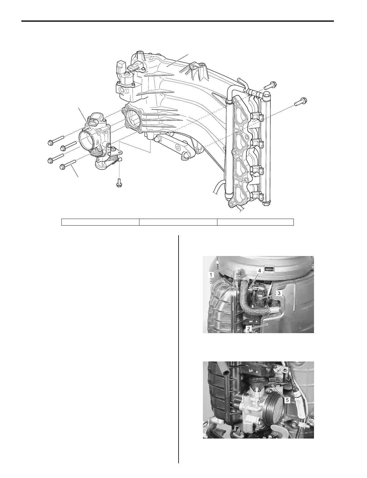
Intake Manifold and Throttle Body Components
Z9J0111406005
Intake Manifold Removal and Installation
Z9J0111406006
Removal
1) Relieve fuel pressure.
Refer to “Fuel Pressure Relief Procedure” in Section
1G (Page 1G-15).
2) Disconnect battery cables from battery.
3) Remove both lower side covers.
Refer to “Lower Side Cover Removal and
Installation” in Section 2A (Page 2A-3).
4) Remove the ring gear cover (1).
Refer to “Ring Gear Cover Removal and Installation”
(Page 1D-2).
5) Remove the air intake silencer case (2).
Refer to “Air Intake Silencer Case Removal and
Installation” (Page 1D-5).
6) Disconnect the IAC valve lead wire connector (3) at
IAC valve.
7) Disconnect the MAP sensor lead wire connector (4)
at sensor.
8) Disconnect the throttle position sensor lead wire
connector (5) at sensor.
1
2
3
I9J011140001-01
1. Intake manifold assembly 2. Throttle body assembly 3. Bolt
I9J011140105-01
I9J011140106-01