Power Unit Mechanical: 1D-6
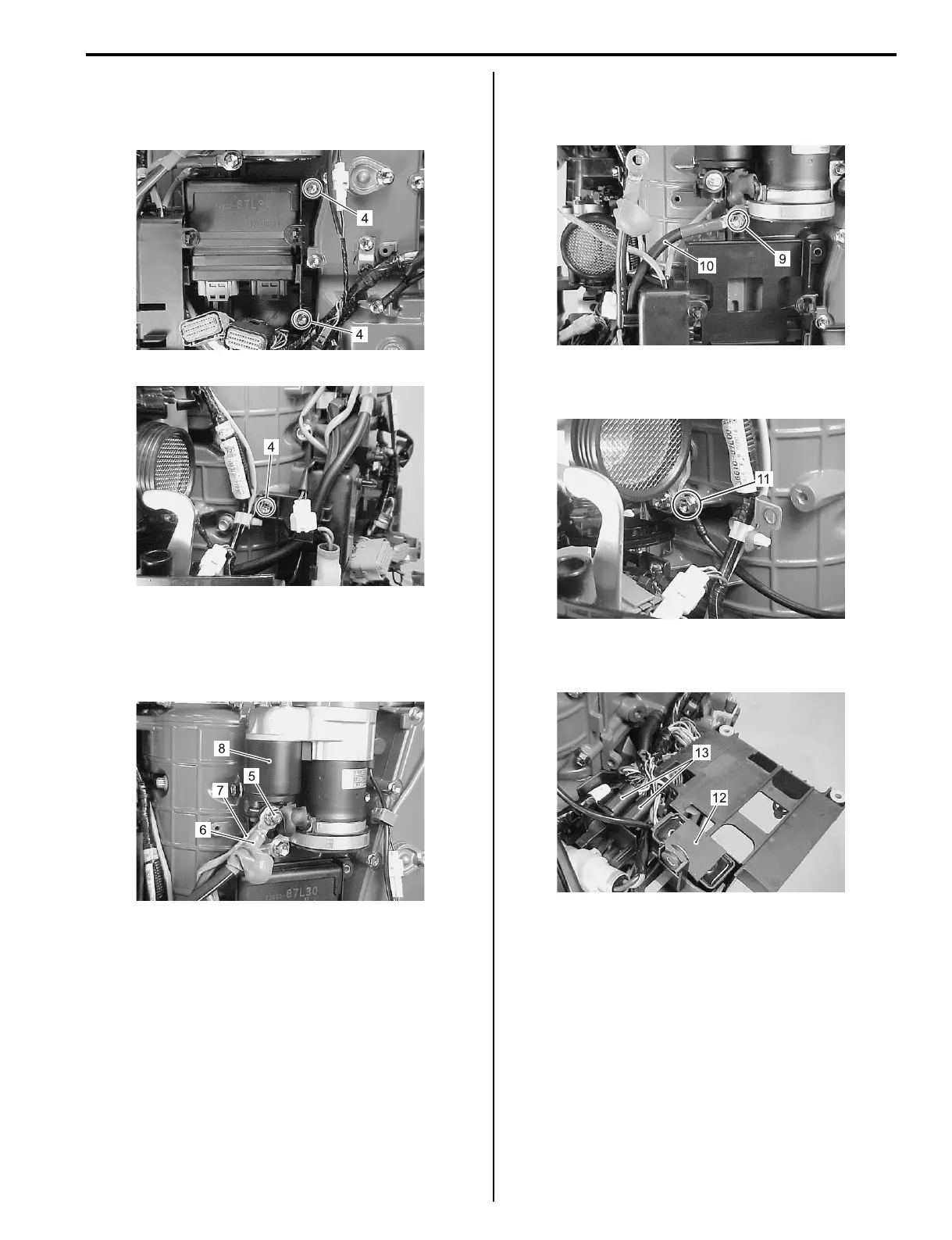
5) Remove the three bolts (4) securing electric parts
holder to cylinder block.
6) Remove ECM from electric parts holder.
7) To remove the electric parts holder, refer to following.
a) Remove nut (5), positive (+) battery cable (6)
and positive lead wire (7) from magnetic switch
(8) of starter motor.
b) Remove the bolt (9) securing negative (–) battery
cable (10).
Pull battery cable out of electric parts holder.
c) Remove the bolt (11) securing PTT motor relay
GND lead wire.
d) Remove PTT motor relay (12) and joint
connectors (13) from electric parts holder.
Installation
Installation is reverse order.
Perform the following final assembly checks to ensure
proper and safe operation.
• All parts removed have been returned to their original
positions.
• Wire routing matches service manual illustration.
Refer to “Wiring Harness Routing Diagram” in Section
4A (Page 4A-3) and “Fuel Hose Routing” in Section
4B (Page 4B-1).
I9J011140099-01
I9J011140100-01
I9J011140101-01
I9J011140102-01
I9J011140103-04
I9J011140104-01