1F-2 Power Unit Cooling System:
Schematic and Routing Diagram
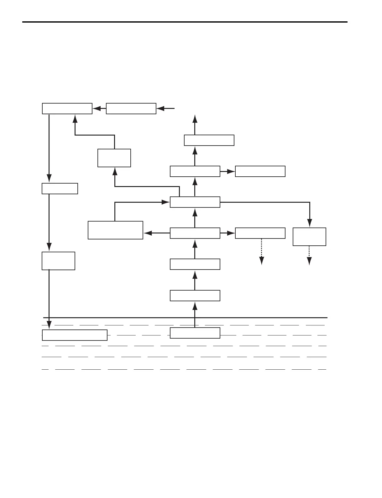
Cooling Water Circulation Chart
Z9J0111602001
The water cooling system includes the lower unit water pump, lower unit to power unit water supply tube, oil pan water
pressure valve, power unit water passages and thermostat.
This system cools both the power unit and exhaust and is shown in schematic form below.
If overheating occurs, the components of the cooling system must be inspected for blockage, corrosion build-up or
component damage.
WATER
Oil pan
Driveshaft
housing
Fuel return
pipe
Oil pan
Water jacket cover
Pilot water
hole
Return hose Thermostat open
Thermostat
Cylinder block Cylinder head
Pressure valve
Engine holder
Oil pan
Water tube
Water pump
Propeller exhaust outlet
Water intake
Engine holder
I9J011160001-02