1C-10 Engine Electrical Devices:
CKP Sensor Removal and Installation
Z9J0111306006
Removal
1) Remove the ring gear cover and air intake silencer
case.
Refer to “Ring Gear Cover Removal and Installation”
in Section 1D (Page 1D-2) and “Air Intake Silencer
Case Removal and Installation” in Section 1D
(Page 1D-5).
2) Disconnect the CKP sensor lead wire connector.
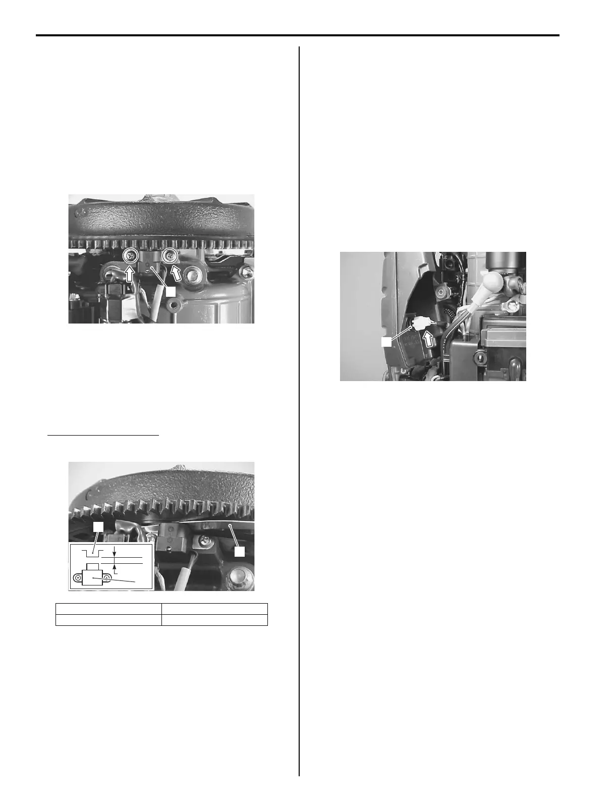
3) Remove the two screws and CKP sensor (1).
Installation
Installation is reverse order of removal with special
attention to the following steps.
• Install CKP sensor with air gap of 0.75 mm between
sensor and reluctor bar on flywheel, then tighten
sensor mounting screws securely.
CKP sensor air gap “a”
0.75 mm (0.030 in.)
• Check to ensure that all removed parts are back in
original position.
• Check wire routing.
Refer to “Wiring Harness Routing Diagram” in Section
4A (Page 4A-3).
CKP Sensor Inspection
Z9J0111306007
Inspect the CKP sensor.
Refer to “Resistance Check” (Page 1C-7).
IAT Sensor Removal and Installation
Z9J0111306008
Removal
1) Remove the ring gear cover and air intake silencer
case.
Refer to “Ring Gear Cover Removal and Installation”
in Section 1D (Page 1D-2) and “Air Intake Silencer
Case Removal and Installation” in Section 1D
(Page 1D-5).
2) Disconnect the IAT sensor lead wire connector.
3) Remove IAT sensor (1).
Installation
Installation is reverse order of removal with special
attention to the following steps.
• Check to ensure that all removed parts are back in
original position.
• Check wire routing.
Refer to “Wiring Harness Routing Diagram” in Section
4A (Page 4A-3).
1. CKP sensor 3. Thickness gauge
2. Reluctor bar
1
I9J011130043-01
2
3
“a”
1
I9J011130044-01
1
I9J011130045-01