1D-33 Power Unit Mechanical:
3) Apply engine oil to cylinder head bolts and tighten
them gradually as follows.
a) Tighten all cylinder head bolts to 50 percent (%)
of specified torque according to sequence in
figure.
Tightening torque
Cylinder head bolt (1st step) [10 mm]: 35
N·m (3.5 kgf-m, 25.5 lbf-ft)
Cylinder head bolt (1st step) [8 mm]: 12 N·m
(1.2 kgf-m, 8.5 lbf-ft)
b) Loosen all cylinder head bolts to 0 N⋅m (0 kgf-m,
0 lbf-ft.) according to reverse sequence in figure.
c) Again tighten all cylinder head bolts to 50
percent (%) of specified torque according to
sequence in figure.
Tightening torque
Cylinder head bolt (3rd step) [10 mm]: 35
N·m (3.5 kgf-m, 25.5 lbf-ft)
Cylinder head bolt (3rd step) [8 mm]: 12 N·m
(1.2 kgf-m, 8.5 lbf-ft)
d) Finally tighten all cylinder head bolts to specified
torque according to sequence in figure.
Tightening torque
Cylinder head bolt (Final step) [10 mm]: 70
N·m (7.0 kgf-m, 50.5 lbf-ft)
Cylinder head bolt (Final step) [8 mm]: 23
N·m (2.3 kgf-m, 16.5 lbf-ft)
4) Install the IN. and EX. camshafts.
Refer to “Camshaft, Tappet and shim Removal and
Installation” (Page 1D-25).
5) Install the timing chain.
Refer to “Timing Chain, Chain Tensioner and
Camshaft Sprockets Removal and Installation”
(Page 1D-20).
Cylinder Head Disassembly and Assembly
Z9J0111406017
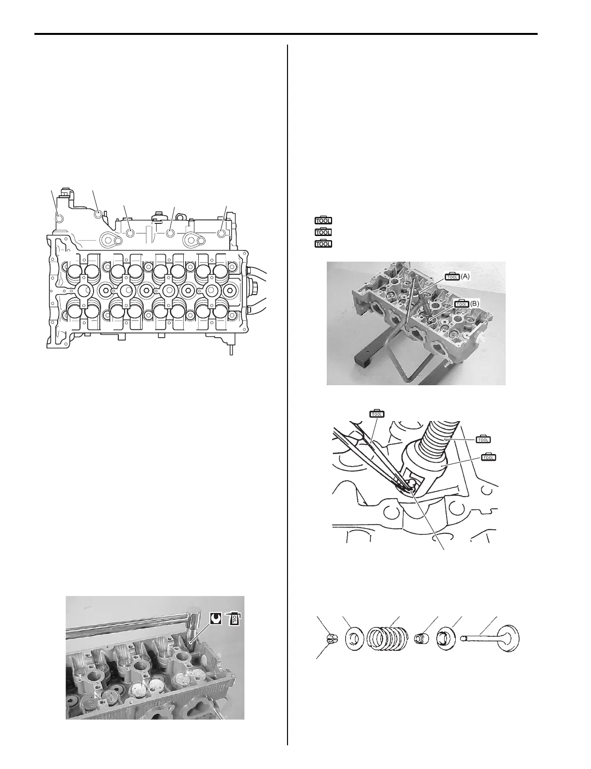
Disassembly
1) Using valve lifter and attachment, remove valve
cotters (1) while compressing valve spring.
Special tool
(A): 09916–19030 (Valve lifter)
(B): 09916–14521 (Valve lifter attachment)
(C): 09916–84511 (Tweezers)
2) Remove valve spring retainer (2), valve spring (3)
and valve (4).
“15”
“8”
“11”
“13”
“12”
“14”
“6”“2”“4”
“10”
“7”
“5”
“1” “3” “9”
I9J011140205-01
I9J011140206-01
I9J011140207-01
1
(A)
(B)
(C)
I9J011140209-01
1
2 3 5 6 4
1
I9J011140210-01