Power Trim and Tilt: 2B-3
Principles of Power Trim and Tilt Operation Description
Z9J0112201002
By motor operation, the geared pump will be driven, and by turning the motor to the right or to the left, oil flow will
change its direction. This causes “UP” and “DOWN” movements of the piston rod of the tilt cylinder.
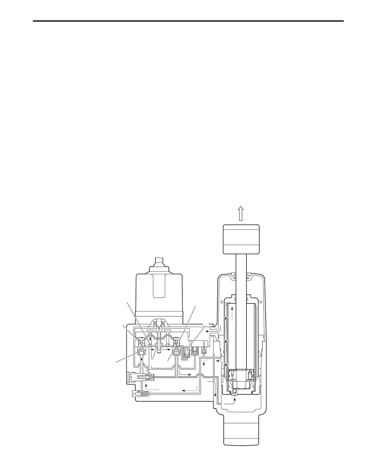
Trim / Tilt Up Circuit
• When the PTT switch is operated “UP” position, the electric motor and gear pump (1) will operation on clockwise
direction.
• Pressurized oil will open check valve (2), oil will flow from the reservoir to spool valve (3) via the pump and spool
valve (4).
• Operation of spool valve (3) in the “DOWN” direction will cause the main check valve (5) to open.
• Oil in the upper chamber of the cylinder will return to the pump via a 2-way valve.
Then the oil pressure will rise and open the “UP” pressure main check valve (6), then allowing oil to flow to the lower
chamber of cylinder.
This makes the piston rod push up and the engine tilt up.
• Oil flows from the reservoir to the pump through check valve (2).
Oil flows through the “DOWN” pressure main check valve (5) and returns to the pump.
• When the trim motor stops, both the “DOWN” pressure main check valve (5) and the “UP” pressure main check
valve (6) will close to retain tilt/trim position.
• In the trim area, the trim piston and floating tube are moving with the piston rod.
• When full tilt up position is attained, sustained operation of the “UP” relay will cause oil flow to be returned to the
reservoir through the “UP” relief valve (7).
1
2
3
5
6
7
4
I9J011220002-01