Power Unit Mechanical: 1D-38
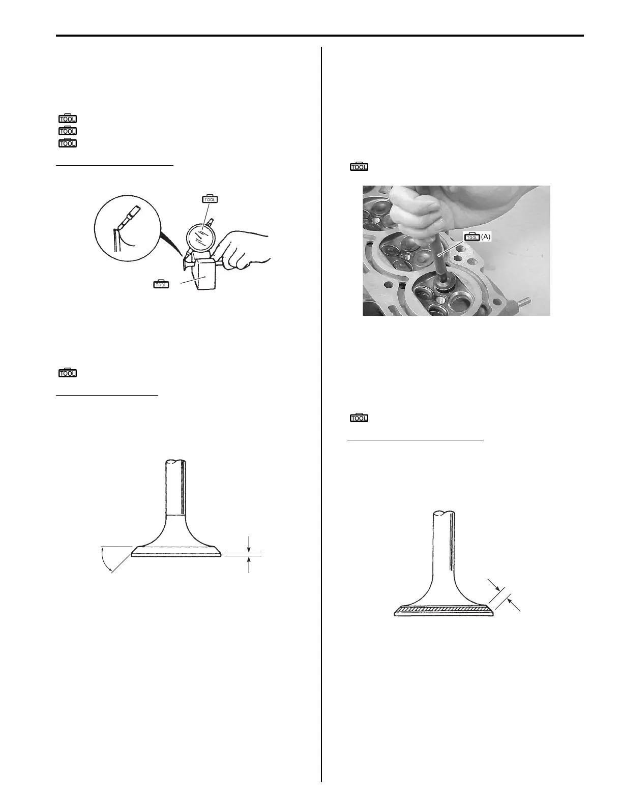
Valve head radial runout
Measure valve head radial runout.
To measure runout, rotate valve slowly.
If measurement exceeds service limit, replace valve.
Special tool
(A): 09900–20606 (Dial gauge)
(B): 09900–21304 (Steel “V” block set)
: 09900–20701 (Magnetic stand)
Valve head radial runout
Service limit: 0.08 mm (0.0031 in.)
Valve head thickness
Measure thickness “a” of valve head.
If measurement exceeds service limit, replace valve.
Special tool
: 09900–20101 (Vernier calipers (150 mm))
Valve head thickness
Standard (IN.): 0.75 mm (0.03 in.)
Standard (EX.): 0.95 mm (0.04 in.)
Service limit (IN.): 0.5 mm (0.02 in.)
Service limit (EX.): 0.7 mm (0.03 in.)
Valve seat contact width
Measure valve seat contact width as follows:
1) Remove all carbon from valve and seat.
2) Coat valve seat evenly with prussian blue (or
equivalent).
3) Install valve into valve guide.
4) Put valve lapper on valve.
Special tool
(A): 09916–10911 (Valve lapper)
5) Rotate valve while gently tapping valve contact area
against seat.
6) Continue until a pattern is on valve seat face with
prussian blue.
7) Measure valve seat contact width “b”.
Special tool
: 09900–20101 (Vernier calipers (150 mm))
Valve seat contact width “b”
Standard (IN., EX.): 1.1 – 1.3 mm (0.0433 – 0.0512
in.)
If measurement exceeds specification, repair valve
seat. Refer to “Valve seat servicing” (Page 1D-39).
(A)
(B)
I9J011140043-03
45°
“a”
I9J011140044-01
I9J011140219-01
“b”
I9J011140045-01