1G-3 Fuel System:
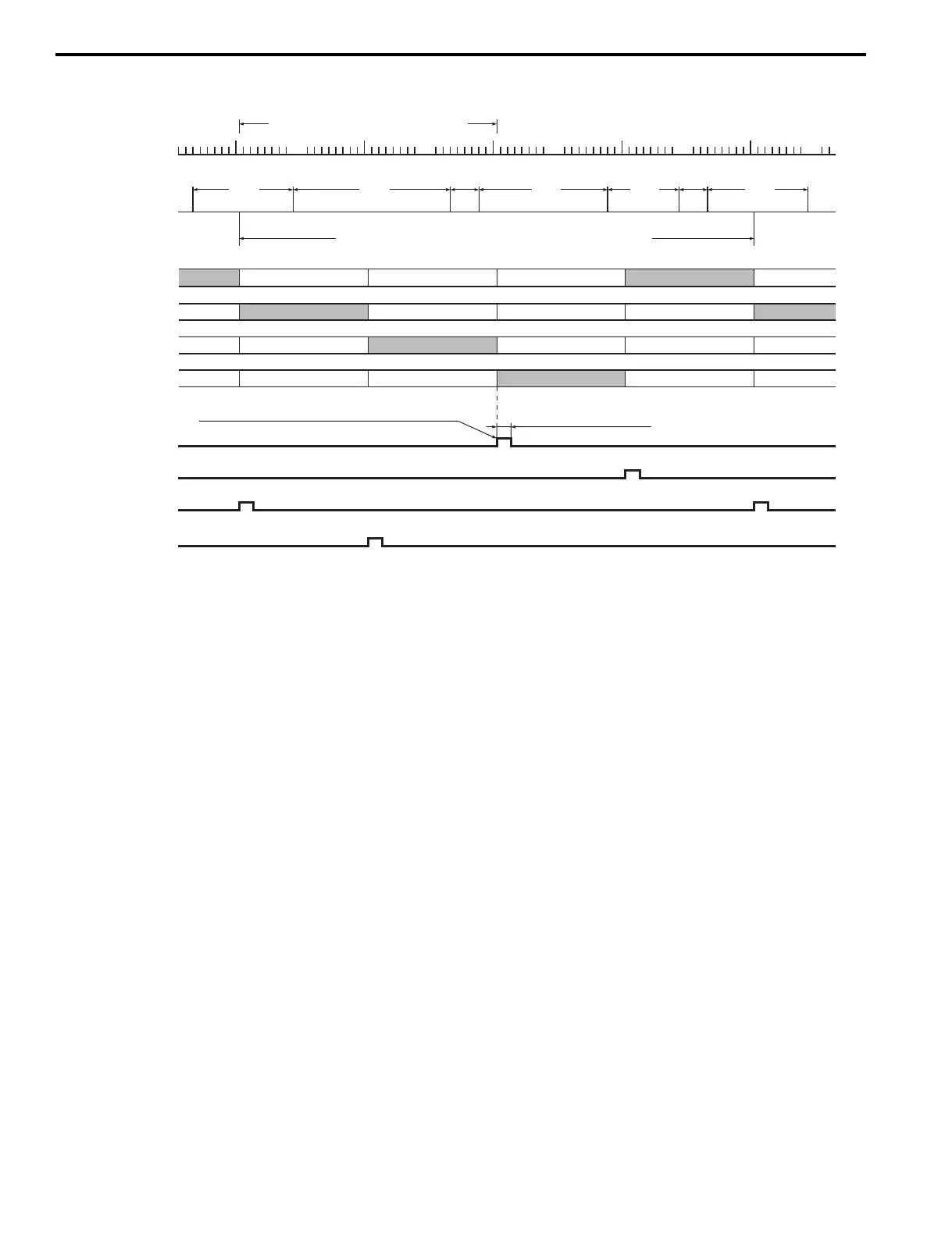
Fuel Injection Timing Chart
Fuel Injection Control Mode
When cranking:
Fuel is injected in each cylinders according to the “Start up mode” map which is based on the cylinder temperature and
intake air temperature (sequential injection).
After start (Fast-idle function):
The fuel injection amount is controlled so that the engine rpm stays within the fast idle speed map until the cylinder
temperature reaches normal operating temperature.
When idling / trolling:
The fuel injection amount is controlled to maintain a stable engine speed at the specified idle / trolling rpm.
When accelerating:
The fuel injection amount is controlled to increase.
When decelerating:
The fuel injection amount is controlled to decrease.
The fuel injection is also cut off on very rapid engine deceleration.
Cm.: Compression, Ep.: Explosion, Ex.: Exhaust, In.: Intake,
No.1 cylinder
No.3 cylinder
No.4 cylinder
No.2 cylinder
CKP sensor
signal
CMP sensor
signal
In.
Ex.
Ep.
Cm.
In.
Ex.
Ep.
Cm.
In.
Ex.
Ep.
Cm.
In.
Ex.
Ep.
Cm.
In.
Ex.
Ep.
Cm.
In.
Ex.
Ep.
Cm.
No.1 Injection
signal
No.3 Injection
signal
No.4 Injection
signal
No.2 Injection
signal
140°
40°
180°
100°
40°
140°
CMP sensor - 6 signals / 720° (crankshaft 2 rotation)
32 signals / crankshaft 1 rotation
Injection end timing: 0° BTDC on Ex.stroke
Injection time duration
TDC
TDC
TDC
TDC
TDC
TDC
TDC
TDC
220°
I9J011170002-05