2B-20 Power Trim and Tilt:
PTT Pump Assembly
• Install four O-rings (1) to PTT body assembly.
NOTE
Lubricate O-rings with PTT fluid before
installing.
• Install PTT pump assembly, then tighten three screws
(a) (b) to specified torque.
Tightening torque
PTT pump assembly bolt (a): 8.0 N·m (0.8 kgf-m,
5.8 lbf-ft)
PTT pump assembly bolt (b): 5.5 N·m (0.55 kgf-
m, 4.0 lbf-ft)
Manual Release Valve
• Oil and install the manual release valve (1).
Tighten the valve to specified torque.
• Install snap ring (2).
Tightening torque
Manual release valve (a): 3.6 N·m (0.36 kgf-m, 2.6
lbf-ft)
PTT Motor
• Install the PTT motor.
Refer to “Power Trim and Tilt Motor Removal and
Installation” (Page 2B-22).
PTT Fluid
• Pour recommended PTT fluid into reservoir to
specified level.
Refer to “Checking PTT Fluid Level” (Page 2B-10).
Air Bleeding
Before installing the PTT unit on the outboard motor, use
the following procedure to bleed air from the system.
1) Support the PTT unit in an upright position in a vise.
2) Fill the reservoir with PTT fluid to the specified level,
then install oil filler plug.
3) Tighten the manual release valve to the specified
torque.
4) Connect the PTT cable extension to the PTT motor
cable connector.
Special tool
(A): 09945–79310 (PTT cable extension)
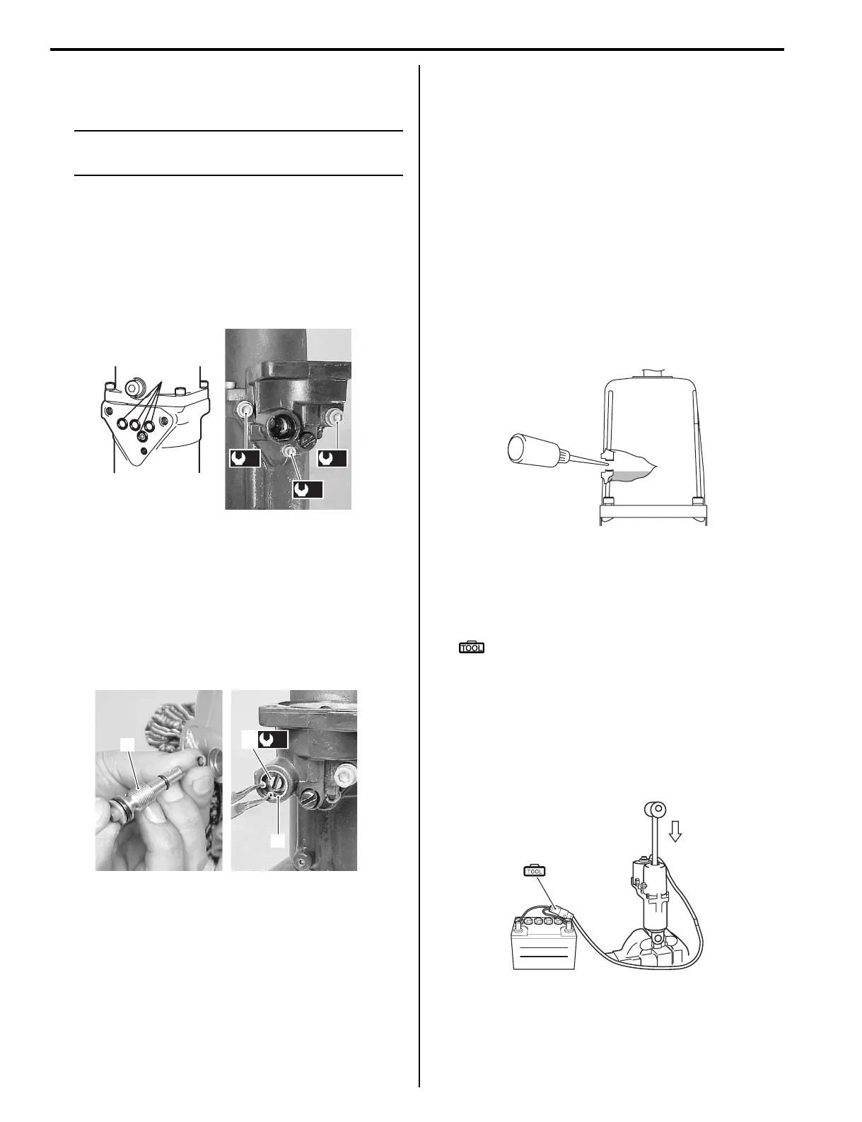
5) Connect the two extension cable lead wires (Bl to
positive / G to negative) to the battery as shown in
the illustration.
Operate the PTT motor until the PTT rod is in the
fully trimmed down position (completely retracted).
If the rod does not come down completely, push it in
by hand while operating the motor.
1
(a) (a)
(b)
I9J011220020-01
1
(a)
1
2
I9J011220021-01
I9J011220022-01
(A)
I9J011220023-01