1A-40 Engine General Information and Diagnosis:
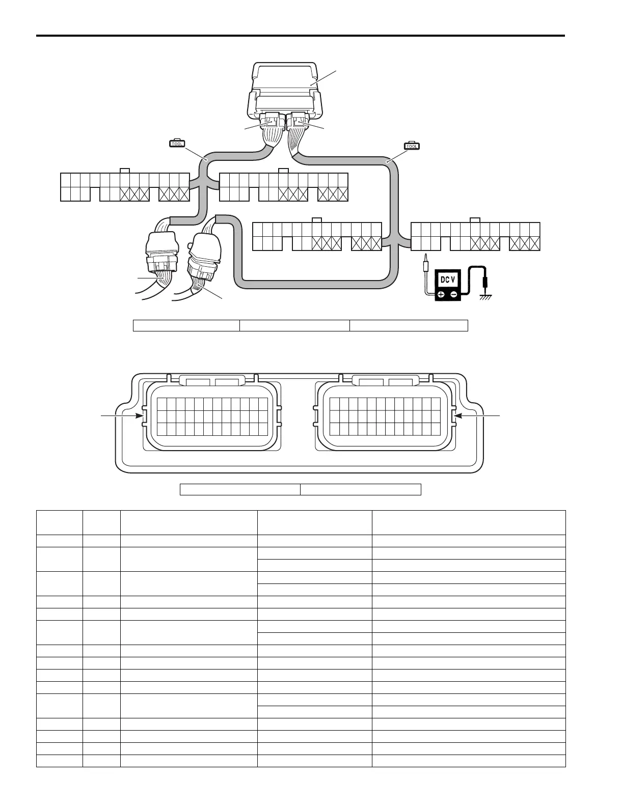
Circuit Voltage Table
37
50
38
51
39
52
40 41
53
42 43 44 45 46 47 48 49 55
68
56
69
57
70
58 59
71
60 61 62 63 64 65 66 67
19 20 21 22 23 24 25 26 27 28 29 30 3112345678910111213
(White connector)
(White connector)
(Black connector)
(Black connector)
14 15 16 17 18
32 33 34 35 36
72
(A)
(A)
1
2
3
3
ECM
54
I9J011110037-02
1. Black connector side 2. Gray connector side 3. Wire harness
12 11 10
987654321
24 23 22 21 20 19 18 17 16 15 14 13
36 35 34 33 32 31 30 29 28 27 26
25
60 59 58 57 56 55 54 53 52 51 50 49
72 71 70 69 68 67 66 65 64 63 62 61
48 47 46 45 44 43 42 41 40 39 38
37
“A”
“B”
I9J011110017-02
“A”: Black connector “B”: Gray connector
Terminal
Wire
color
Circuit Standard Voltage Condition / Remarks
1— — — —
2 G Starter relay control
Approx. 0.5 V Ignition switch ON, Cranking.
Approx. 12 V Ignition switch ON, Normal.
3 P/W PTT relay DN
Approx. 0 V PTT switch DN, free.
Approx. 12 V PTT switch DN, Push.
4— — — —
5 Bl/B Water pressure sensor 0.5 – 4.5 V Ignition switch ON.
6 Br/Y Throttle position sensor
Approx. 3.8 V Ignition switch ON, Throttle WOT.
Approx. 0.7 V Ignition switch ON, Throttle FCT.
7 W/Y Trim and Tilt sensor Approx. 0.9 – 4.0 V Ignition switch ON.
8 Lg/B IAT sensor 0.04 – 4.46 V Ignition switch ON.
9 Bl/W Speedo sensor 0.5 – 4.5 V Ignition switch ON.
10 R/W Power source #2 for sensor Approx. 5 V Ignition switch ON.
11 Bl Oil pressure switch
Approx. 5 V While engine running.
Approx. 0 V Engine stopped (Ignition switch ON.)
12 Gr ECM power source Approx. 12 V Ignition switch ON.
13 — — — —
14 — — — —
15 B/G Ignition switch key Approx. 12 V Ignition switch ON.