SPM shift
6-327
SPM shift Set Product Mode Shift Bits
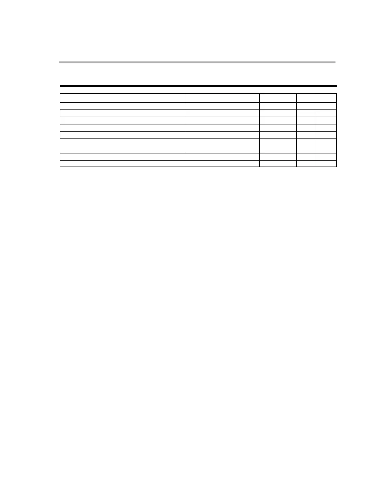
SYNTAX OPTIONS OPCODE OBJMODE RPT CYC
SPM +1 1111 1111 0110 1000 X − 1
SPM 0 1111 1111 0110 1001 X − 1
SPM −1 1111 1111 0110 1010 X − 1
SPM −2 1111 1111 0110 1011 X − 1
SPM −3 1111 1111 0110 1100 X − 1
SPM −4 (Valid only when AMODE = 0)
SPM +4 (Valid only when AMODE = = 1)
1111 1111 0110 1101 X − 1
SPM −5 1111 1111 0110 1110 X − 1
SPM −6 1111 1111 0110 1111 X − 1
Operands
shift
Product shift mode (+4, +1, 0, −1, −2, −3, −4, −5, −6)
Description Specify a product shift mode. A negative value indicates an arithmetic right
shift; positive numbers indicate a logical left shift. The following table shows
the relationship between the “shift” operand and the 3-bit value that gets
loaded into the product shift mode (PM) bits in ST0. The address mode bit
(AMODE) selects between two types of shift decodes as shown in the table
below:
PM Bits AMODE = 1
AMODE = 0
000 SPM +1 SPM +1
001 SPM 0 SPM 0
010 SPM −1 SPM −1
011 SPM −2 SPM −2
100 SPM −3 SPM −3
101 SPM +4 SPM −4
110 SPM −5 SPM −5
111 SPM −6 SPM −6
Flags and
Modes
PM
PM is loaded with the 3-bit value specified by the selected ”shift” value.
Repeat This instruction is repeatable. If the operation follows a RPT instruction, then
the SFR instruction will be executed N+1 times. The state of the Z, N and C
flags will reflect the final result.