Analog-to-Digital Converter (ADC)
TMS320F2837xD Microcontroller Workshop - Analog Subsystem 6 - 9
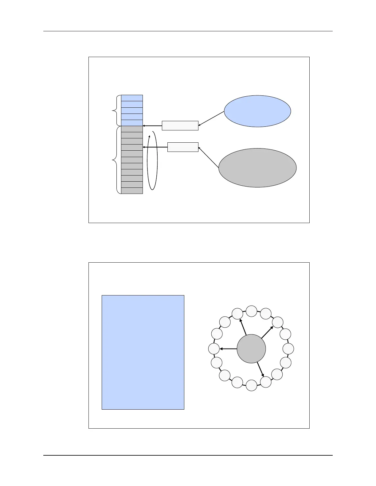
Conversion Priority Functional Diagram
Round Robin Pointer
Points to the last converted
round robin SOCx and
determines order
of conversions
SOC Priority
Determines cutoff point
for high priority and
round robin mode
SOC0
SOC1
SOC2
SOC3
SOC4
SOC5
SOC6
SOC7
SOC8
SOC9
SOC10
SOC11
SOC12
SOC13
SOC14
SOC15
Round Robin
High Priority
SOCPRIORITY
RRPOINTER
AdcRegs.SOCPRICTL
In this conversion priority functional diagram, the Start-of-Conversion Priority Control Register
contains two bit fields. The Start-of-Conversion Priority bit fields determine the cutoff point
between high priority and round robin mode, whereas the Round-Robin Pointer bit fields contains
the last converted round robin start-of-conversion which determines the order of conversions.
Round Robin Priority Example
SOC
0
SOC
1
SOC
2
SOC
3
SOC
4
SOC
5
SOC
6
SOC
7
SOC
8
SOC
9
SOC
10
SOC
11
SOC
12
SOC
13
SOC
14
SOC
15
RRPOINTER
SOC7 trigger received
SOC7 is converted;
RRPOINTER now points to SOC7;
SOC8 is now highest RR priority
SOC2 & SOC12 triggers received
simultaneously
SOC12 is converted;
RRPOINTER points to SOC12;
SOC13 is now highest RR priority
SOC2 is converted;
RRPOINTER points to SOC2;
SOC3 is now highest RR priority
SOCPRIORITY configured as 0;
RRPOINTER configured as 15;
SOC0 is highest RR priority

 Loading...


