Analog-to-Digital Converter (ADC)
6 - 10 TMS320F2837xD Microcontroller Workshop - Analog Subsystem
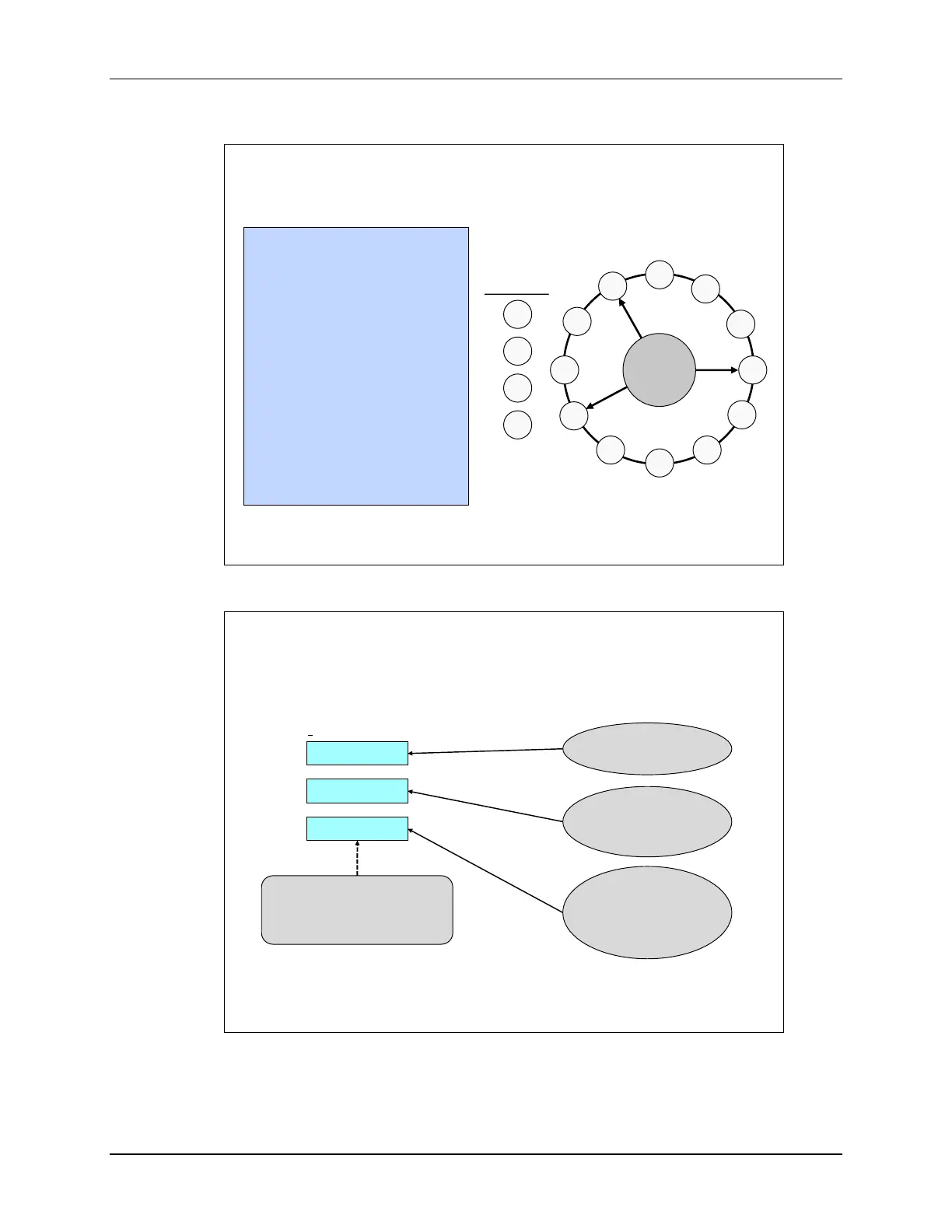
High Priority Example
SOC
4
SOC
5
SOC
0
SOC
6
SOC
7
SOC
8
SOC
9
SOC
10
SOC
11
SOC
12
SOC
13
SOC
14
SOC
15
RRPOINTER
SOC
1
SOC
2
SOC
3
High Priority
SOC7 trigger received
SOC7 is converted;
RRPOINTER points to SOC7;
SOC8 is now highest RR priority
SOC2 is converted;
RRPOINTER stays pointing to SOC7
SOC12 is converted;
RRPOINTER points to SOC12;
SOC13 is now highest RR priority
SOCPRIORITY configured as 4;
RRPOINTER configured as 15;
SOC4 is highest RR priority
SOC2 & SOC12 triggers received
simultaneously
Round Robin Burst Mode Diagram
Burst Enable
Disables/enables burst mode
BURSTEN
AdcxRegs.ADCBURSTCTL
BURSTSIZE
BURSTTRIGSEL
SOC Burst Size
Determines how many
SOCs are converted per
burst trigger
SOC Burst Trigger
Source Select
Determines which trigger
starts a burst conversion
sequence
Software, CPU1 Timer0-2
ePWM1 ADCSOCA/C – B/D
ePWM12 ADCSOCA/C – B/D
CPU2 Timer0-2
The Round-Robin Burst mode utilizes an ADC Burst Control Register to enable the burst mode,
determine the burst size, and select the burst trigger source.

 Loading...


