eCAP
7 - 42 TMS320F2837xD Microcontroller Workshop - Control Peripherals
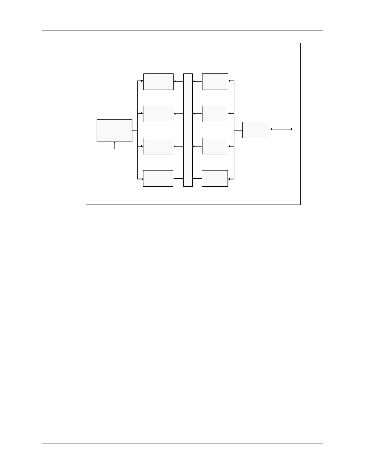
eCAP Module Block Diagram
– Capture Mode
32-Bit
Time-Stamp
Counter
Capture 1
Register
Event
Prescale
Polarity
Select 1
Polarity
Select 2
Polarity
Select 3
Polarity
Select 4
Capture 2
Register
Capture 3
Register
Capture 4
Register
Event Logic
ECAPx
pin
CAP1POL
CAP2POL
CAP3POL
CAP4POL
PRESCALE
CPUx.SYSCLK
The eCAP module captures signal transitions on a dedicated input pin and sequentially loads a
32-bit time-base counter value in up to four 32-bit time-stamp capture registers (CAP1 – CAP4).
By using a 32-bit counter, rollover is minimized. Independent edge polarity can be configured as
rising or falling edge, and the module can be run in either one-shot mode for up to four time-
stamp events or continuous mode to capture up to four time-stamp events operating as a circular
buffer. The capture input pin is routed through the Input X-Bar, allowing any GPIO pin on the
device to be used as the input. Also, the input capture signal can be pre-scaled and interrupts
can be generated on any of the four capture events. The time-base counter can be run in either
absolute or difference (delta) time-stamp mode. In absolute mode the counter runs continuously,
whereas in difference mode the counter resets on each capture

 Loading...


