Home
Texas Instruments
Microcontrollers
TMS320F2837 D Series
Workshop Guide And Lab Manual
Page 248
Texas Instruments TMS320F2837 D Series - Page 248
324 pages
Manual
To Next Page
To Next Page
To Previous Page
To Previous Page
Loading...
Lab 9: CL
A Floatin
g
-
Poin
t FIR
Filte
r
9 -
24
TMS320F2
837xD
Microcon
troller W
orks
hop
-
Control L
aw Accel
erator
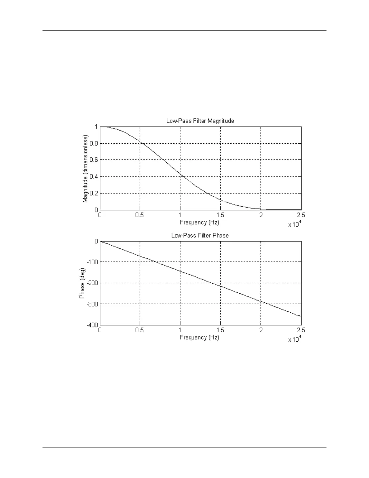
Lab 9 Reference:
Low
-
Pass FI
R Filter
Bode P
lot o
f Dig
ital L
ow
Pass
Filter
Coeff
icients: [1/16,
4/16, 6/
16, 4/16,
1/16]
Sample Rat
e: 50 k
Hz
247
249
Table of Contents
Main Page
Section 1
10
Architecture Overview
9
Table of Contents
10
Introduction to the Tms320F28X7X
11
C28X Internal Bussing
12
C28X CPU + FPU + VCU + TMU and CLA
13
Special Instructions
14
CPU Pipeline
15
C28X CPU + FPU + VCU + TMU Pipeline
16
Peripheral Write-Read Protection
17
Memory
18
Memory Map
18
Dual Code Security Module (DCSM)
19
Peripherals
19
Fast Interrupt Response Manager
20
Math Accelerators
21
Viterbi / Complex Math Unit (VCU-II)
21
Trigonometric Math Unit (TMU)
22
On-Chip Safety Features
23
Summary
24
Section 2
26
Programming Development Environment
27
Code Composer Studio
27
Software Development and COFF Concepts
27
Edit and Debug Perspective (Ccsv7)
29
Target Configuration
30
Ccsv7 Project
31
Creating a New Ccsv7 Project
32
Ccsv7 Build Options - Compiler / Linker
33
CCS Debug Environment
34
Creating a Linker Command File
36
Sections
36
Linker Command Files (.CMD)
39
Memory-Map Description
39
Section Placement
40
Summary: Linker Command File
41
Lab File Directory Structure
42
Lab 2: Linker Command File
43
Section 3
50
Register Programming Model
51
Traditional and Structure Approach to C Coding
53
Naming Conventions
57
F2837Xd C-Code Header Files
59
Peripheral Structure .H File
59
Global Variable Definitions File
61
Mapping Structures to Memory
62
Linker Command File
62
Peripheral Specific Routines
63
Summary
64
Section 4
66
Reset and Boot Process
67
Reset - Bootloader
69
Emulation Boot Mode
70
Stand-Alone Boot Mode
71
Reset Code Flow - Summary
72
Emulation Boot Mode Using Code Composer Studio GEL
72
Getting to Main()
73
Peripheral Software Reset Registers
74
Interrupts
75
Interrupt Processing
76
Interrupt Flag Register (IFR)
77
Interrupt Enable Register (IER)
77
Interrupt Global Mask Bit (INTM)
78
Peripheral Interrupt Expansion (PIE)
78
PIE Block Initialization
81
Interrupt Signal Flow - Summary
83
F2837Xd Dual-Core Interrupt Structure
84
Interrupt Response and Latency
85
Section 5
88
Oscillator/Pll Clock Module
89
F2837Xd Dual-Core System Clock
91
Watchdog Timer
93
General Purpose Digital I/O
98
GPIO Input X-Bar
101
GPIO Output X-Bar
102
External Interrupts
104
Low Power Modes
105
Register Protection
107
Lab 5: System Initialization
109
Section 6
117
Analog-To-Digital Converter (ADC)
119
ADC Block and Functional Diagrams
119
ADC Triggering
121
ADC Conversion Priority
122
Post Processing Block 1
127
ADC Clocking Flow
128
ADC Registers
128
Signed Input Voltages
133
ADC Calibration and Reference
134
Comparator Subsystem (CMPSS)
136
Comparator Subsystem Block Diagram
137
Digital-To-Analog Converter (DAC)
138
Buffered DAC Block Diagram
139
Sigma Delta Filter Module (SDFM)
140
SDFM Block Diagram
141
Lab 6: Analog-To-Digital Converter
142
Section 7
152
Control Peripherals
153
PWM Review
153
Epwm
155
Epwm Time-Base Sub-Module
157
Epwm Compare Sub-Module
161
Epwm Action Qualifier Sub-Module
164
Asymmetric and Symmetric Waveform Generation Using the Epwm
172
PWM Computation Example
173
Epwm Dead-Band Sub-Module
174
Epwm Chopper Sub-Module
177
Epwm Trip-Zone and Digital Compare Sub-Modules
180
Epwm Event-Trigger Sub-Module
188
High Resolution PWM (HRPWM)
190
Ecap
191
Eqep
197
Lab 7: Control Peripherals
200
Section 8
208
Direct Memory Access
209
Direct Memory Access (DMA)
209
Basic Operation
210
DMA Examples
212
Channel Priority Modes
215
DMA Throughput
216
DMA Registers
217
Lab 8: Servicing the ADC with DMA
221
Section 9
226
Control Law Accelerator
227
Control Law Accelerator (CLA)
227
CLA Block Diagram
228
CLA Memory and Register Access
228
CLA Tasks
229
CLA Control and Execution Registers
230
CLA Registers
231
CLA Initialization
234
CLA Task Programming
235
CLA C Language Implementation and Restrictions
235
CLA Assembly Language Implementation
238
CLA Code Debugging
241
Lab 9: CLA Floating-Point FIR Filter
242
Section 10
250
External Memory Interface (EMIF)
253
Flash Configuration and Memory Performance
255
Flash Programming
258
Dual Code Security Module (DCSM)
260
Lab 10: Programming the Flash
264
Section 11
272
Inter-Processor Communications
273
IPC Global Shared RAM and Message RAM
273
Interrupts and Flags
275
IPC Data Transfer
277
Lab 11: Inter-Processor Communications
279
Section 12
286
Communications
287
Communications Techniques
287
Serial Peripheral Interface (SPI)
288
SPI Summary
291
Multiprocessor Wake-Up Modes
294
Definition: Bit, Word, and Frame
298
Multi-Channel Selection
299
Mcbsp Summary
299
Inter-Integrated Circuit (I2C)
300
I2C Operating Modes and Data Formats
301
I2C Summary
302
Universal Serial Bus (USB)
303
USB Communication
304
Enumeration
304
F28X USB Hardware
305
USB Controller Summary
305
Controller Area Network (CAN)
306
CAN Bus and Node
307
Principles of Operation
308
Message Format and Block Diagram
309
CAN Summary
310
Support Resources
313
TI Support Resources
313
C2000 Workshop Download Wiki
313
Documentation Resources
314
C2000Ware
314
C2000 Experimenter's Kit
315
F28335 Peripheral Explorer Kit
316
C2000 Launchpad Evaluation Kit
317
C2000 Controlcard Application Kits
318
XDS100 / XDS200 Class JTAG Debug Probes
319
Product Information Resources
320
Other manuals for Texas Instruments TMS320F2837 D Series
Manual
52 pages
Errata Sheet
48 pages
Related product manuals
Texas Instruments TMS320F28069
177 pages
Texas Instruments TMS570LS0714
162 pages
Texas Instruments TMS570LC4357
2208 pages
Texas Instruments TM4C1294NCPDT
1890 pages
Tiva TM4C123GH6PM
352 pages
Texas Instruments TAS6584-Q1 EVM
26 pages
Texas Instruments TPS65941120-Q1
55 pages
Texas Instruments CC2541
29 pages
Texas Instruments CC253x
370 pages
Texas Instruments CC2540
29 pages
Texas Instruments RM46L852
173 pages
Texas Instruments MSP430 series
191 pages

 Loading...


