Lab 11: Inter-Processor Communications
TMS320F2837xD Microcontroller Workshop - Dual-Core Inter-Processor Communications 11 - 11
In IPC1_ISR() the incoming ADC result value from CPU1 is read via the IPCRECVDATA
register, and the sine data to CPU1 is written via the IPCSENDADDR register. The
IPCSENDDATA and IPCRECVDATA registers are mapped to the same address on each CPU,
as are the IPCSENDADDR and IPCRECVADDR registers.
Jumper Wire Connection
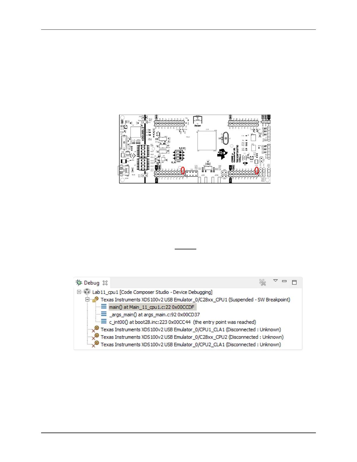
8. Using a jumper wire, connect the ADCINA0 (header J3, pin #30) to DACB (header J7, pin
#70) on the LaunchPad. Refer to the following diagram for the pins that need to be
connected.
Build and Load the Project
9. In the Project Explorer window click on the Lab11_cpu01 project to set it active. Then click
the Build button and watch the tools run in the Console window. Check for any errors in the
Problems window. Repeat this step for the Lab11_cpu02 project.
10. Again, in the Project Explorer window click on the Lab11_cpu01 project to set it active. Click
on the Debug button (green bug). A Launching Debug Session window will open. Select
only CPU1 to load the program on (i.e. uncheck CPU2), and then click OK. The CCS Debug
perspective view should open, then CPU1 will connect to the target and the program will load
automatically.
11. The Debug window reflects the current status of CPU1 and CPU2.
Notice that CPU1 is currently connected and CPU2 is “Disconnected”. This means that CCS
has no control over CPU2 thus far; it is freely running from the view of CCS. Of course CPU2
is under control of CPU1 and since we have not executed an IPC command yet, CPU2 is
stopped by an “Idle” mode instruction in the Boot ROM.
12. Next, we need to connect to and load the program on CPU2. Right-click at the line “Texas
Instruments XDS100v2 USB Emulator_0/C28xx_CPU2” and select Connect Target.
13. With the line “Texas Instruments XDS100v2 USB Emulator_0/C28xx_CPU2” still highlighted,
load the program:

 Loading...


