Lab 11: Inter-Processor Communications
11 - 12 TMS320F2837xD Microcontroller Workshop - Dual-Core Inter-Processor Communications
Run Load Load Program…
Browse to the file: C:\C28x\Labs\Lab11\cpu02\Debug\Lab11_cpu02.out and select
OK to load the program.
14. Again, with the line “Texas Instruments XDS100v2 USB Emulator_0/C28xx_CPU1”
highlighted, set the bootloader mode using the menu bar by clicking:
Scripts EMU Boot Mode Select EMU_BOOT_SARAM
Use the same procedure above to set the bootloader mode for CPU2. If the device has been
power cycled between lab exercises, or within this lab exercise, be sure to configure the boot
mode to EMU_BOOT_SARAM using the Scripts menu for both CPU1 and CPU2.
Run the Code
15. In the Debug window, click on the line “Texas Instruments XDS100v2 USB
Emulator_0/C28xx_CPU1”. Run the code on CPU1 by clicking the green Resume button. At
this point CPU1 is waiting for CPU2 to be ready.
16. In the Debug window, click on the line “Texas Instruments XDS100v2 USB
Emulator_0/C28xx_CPU2”. As before, run the code on CPU2 by clicking the Resume button.
Using the IPC17, CPU2 communicates to CPU1 that it is now ready. On the LaunchPad,
LED D9 connected to CPU1 should be blinking at approximately 1 Hz and LED D10
connected to CPU2 should be blinking at approximately 5 Hz.
17. In the Debug window select CPU1. Halt the CPU1 code after a few seconds by clicking on
the Suspend button.
18. Then in the Debug window select CPU2. Halt the CPU2 code by using the same procedure.
View the ADC Results
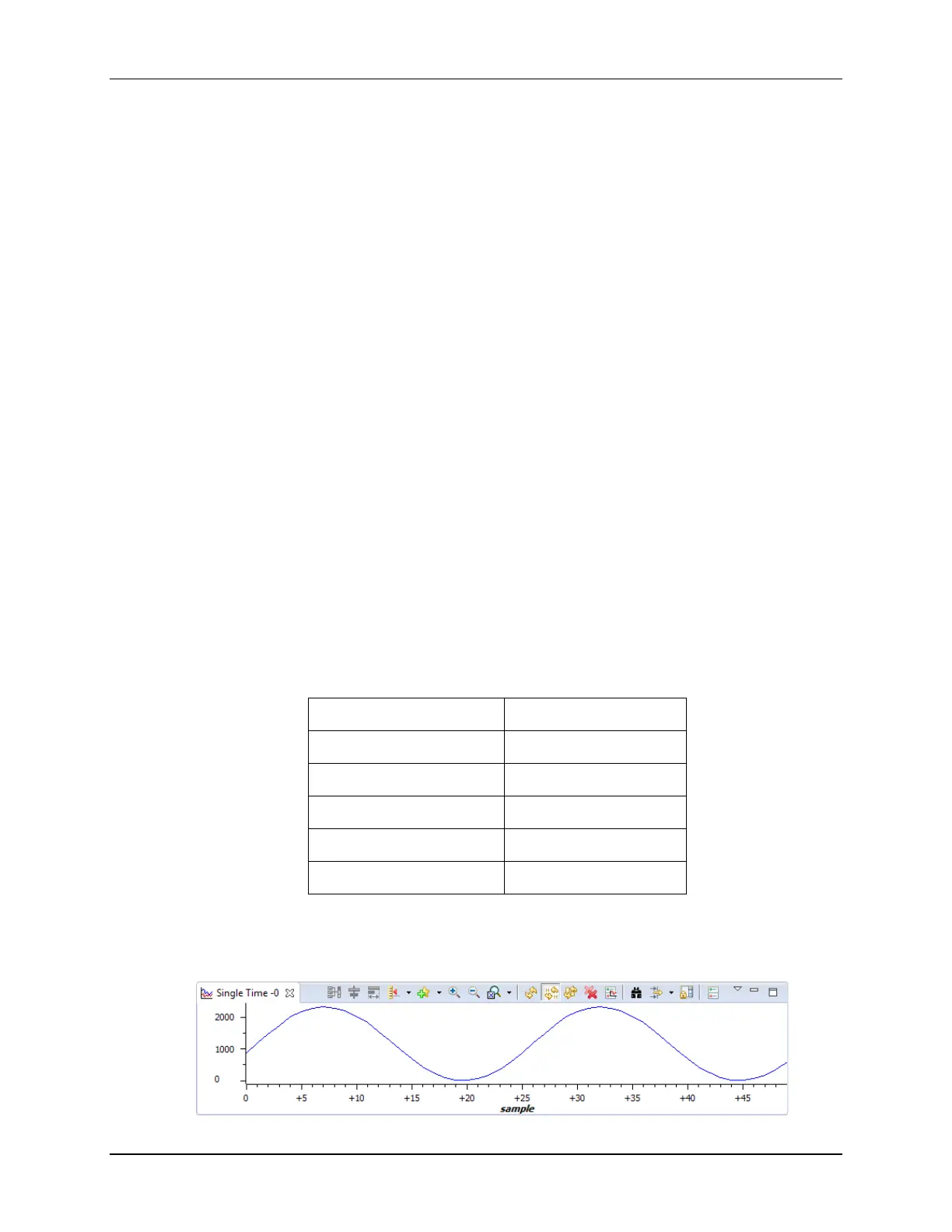
19. Open and setup a graph to plot a 50-point window of the ADC results buffer.
Click: Tools Graph Single Time and set the following values:
Acquisition Buffer Size 50
DSP Data Type 16-bit unsigned integer
Sampling Rate (Hz) 50000
Start Address AdcBuf
Display Data Size 50
Time Display Unit sample
Select OK to save the graph options.
20. If the IPC communications is working, the ADC results buffer on CPU2 should contain the
sine data transmitted from the look-up table. The graph view should look like:

 Loading...


