Lab 2: Linker Command File
2 - 22 TMS320F2837xD Microcontroller Workshop - Programming Development Environment
cla1, the “Specify floating point support” is set to fpu32, the “Specify TMU support” is set to
TMU0, and the “Specify VCU support” is set to vcu2. Select OK to close the Properties
window.
Linker Command File – Lab2.cmd
16. Open and inspect Lab2.cmd by double clicking on the filename in the Project Explorer
window. Notice that the Memory{} declaration describes the system memory shown on the
“Lab2: Linker Command File” slide in the objective section of this lab exercise. Memory
blocks RAMLS4, RAMLS5 and RAMGS0123 have been placed in program memory on page
0, and the other memory blocks have been placed in data memory on page 1.
17. In the Sections{} area notice that the sections defined on the slide have been “linked” into
the appropriate memories. Also, notice that a section called .reset has been allocated. The
.reset section is part of the rts2800_fpu32.lib and is not needed. By putting the TYPE =
DSECT modifier after its allocation the linker will ignore this section and not allocate it. Close
the inspected file.
Build and Load the Project
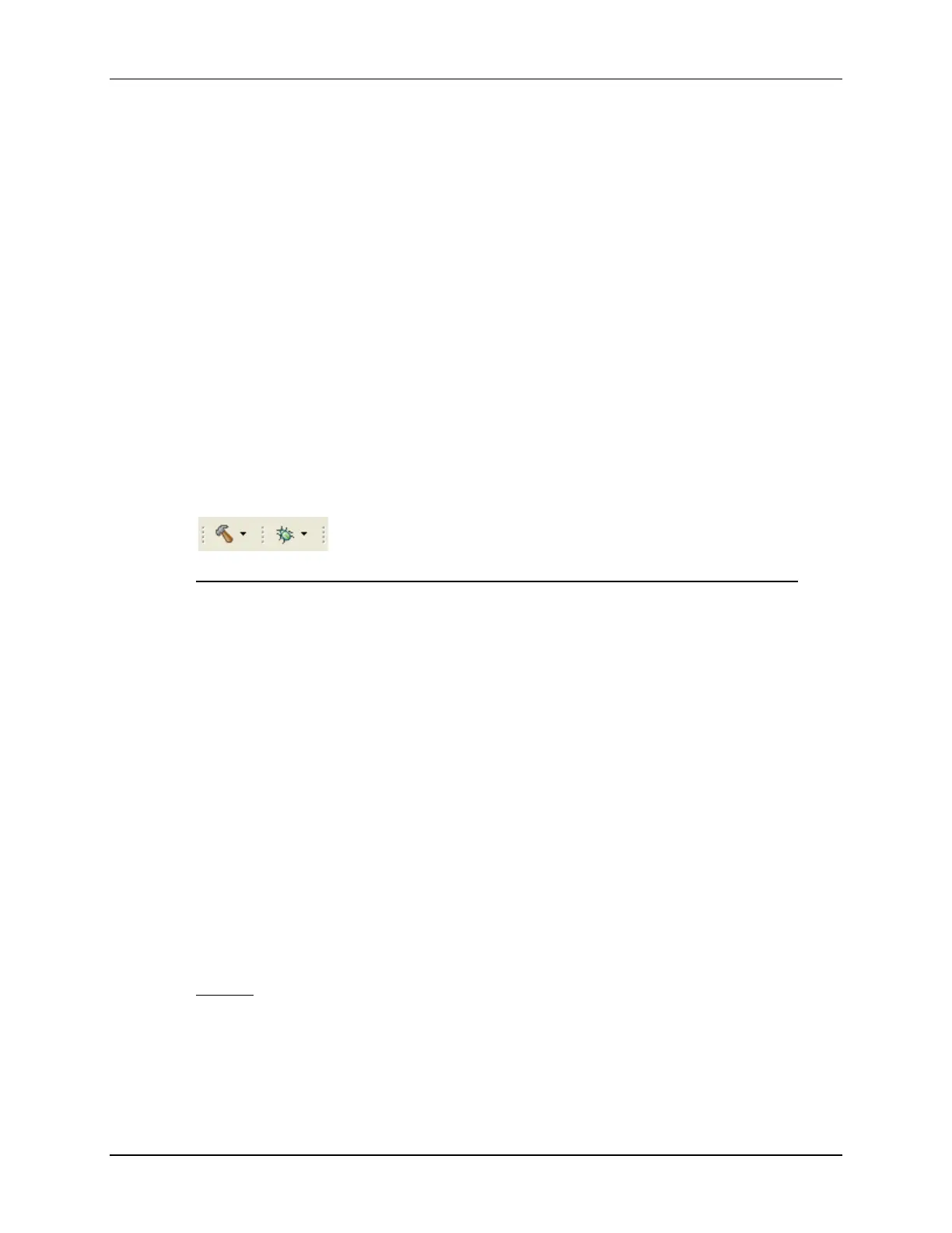
18. Two buttons on the horizontal toolbar control code generation. Hover your mouse over each
button as you read the following descriptions:
Button Name Description_____________________________________
1 Build Full build and link of all source files
2 Debug Automatically build, link, load and launch debug-session
19. Click the “Build” button and watch the tools run in the Console window. Check for errors in
the Problems window (we have deliberately put an error in Lab2.c). When you get an error,
you will see the error message in the Problems window. Expand the error by clicking on the
plus sign (+) to the left of the “Errors”. Then simply double-click the error message. The
editor will automatically open to the source file containing the error, with the code line
highlighted with a red circle with a white “x” inside of it.
20. Fix the error by adding a semicolon at the end of the “z = x + y” statement. For future
knowledge, realize that a single code error can sometimes generate multiple error messages
at build time. This was not the case here.
21. Build the project again. There should be no errors this time.
22. CCS can automatically save modified source files, build the program, open the debug
perspective view, connect and download it to the target, and then run the program to the
beginning of the main function.
Click on the “Debug” button (green bug) or click RUN Debug
A Launching Debug Session window will open. Select only CPU1 to load the program on (i.e.
uncheck CPU2), and then click OK.
Notice the “CCS Debug” icon in the upper right-hand corner indicating that we are now in the
CCS Debug perspective view. The program ran through the C-environment initialization
routine in the rts2800_fpu32.lib and stopped at main() in Lab2.c.

 Loading...


