5-6 4262930-Rev A
POWER TRAIN
5
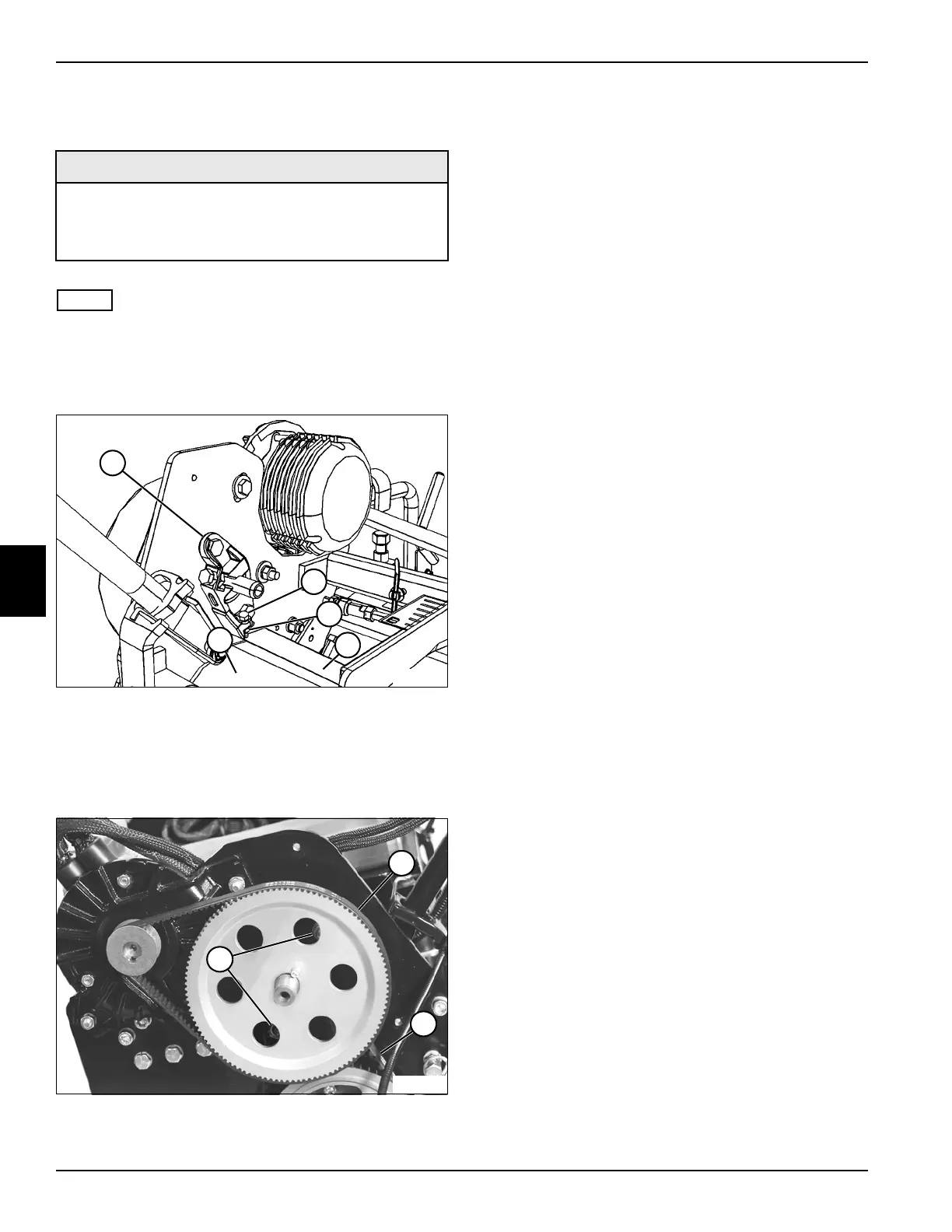
Adjustment Procedure
See Figures 5-4 and 5-5.
NOTE
Minor adjustments to the traction drive (transfer) belt can
be made by pivoting the traction motor mount assembly.
If belt cannot be tensioned to specification, proceed with
the following procedure.
Figure 5-4
1. Install a 5/16-18 x 1" hex screw (2) and nut (3) in the
bottom of the bearing bracket (1).
2. Place the height-of-cut gauge bar (4) between the
traction drum (5) and hex screw (2).
Figure 5-5
3. Loosen nuts (6).
4. Tighten hex screw (2) until the traction drive (final
drive) belt (7) deflects 0.10 in. (2.5 mm) when 12.5–
15.2 lb (55.6–67.6 N) of force is applied at the
midpoint of the belt.
5. Tighten hex screw (2) until the traction drive
(transfer) belt (8) deflects 0.14 in. (3.5 mm) when
3.5–6.3 lb (15.6–28.0 N) of force is applied at the
midpoint of the belt.
6. Tighten nuts (6).
7. Remove the height-of-cut gauge bar (4), hex screw
(2), and nut (3).
8. Install the traction drive belt cover. (See “Traction
Drive Belt Cover” on page 5-7.)
Required Tools and Materials
• Height-of-Cut Gauge Bar
• 5/16-18 x 1" Hex Screw
• 5/16-18 Hex Nut
4
TN0976
3
1
2
5
~
~
4
TN4639
8
6
7