6-6 4262930-Rev A
HANDLE AND CONTROLS
6
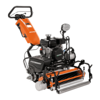
Figure 6-11: Gen-Set Models
10. Disconnect the battery pack/gen-set connector (8).
Figure 6-12
NOTE
Label all wires before disconnecting to ensure correct
installation.
11. Disconnect reel motor controller harness connectors
(9) and traction motor controller harness connectors
(10).
12. For models 63336, 63337, 63345, and 63346,
proceed to next step. For models 63340, 63341,
63349, and 63350, proceed to step 19.
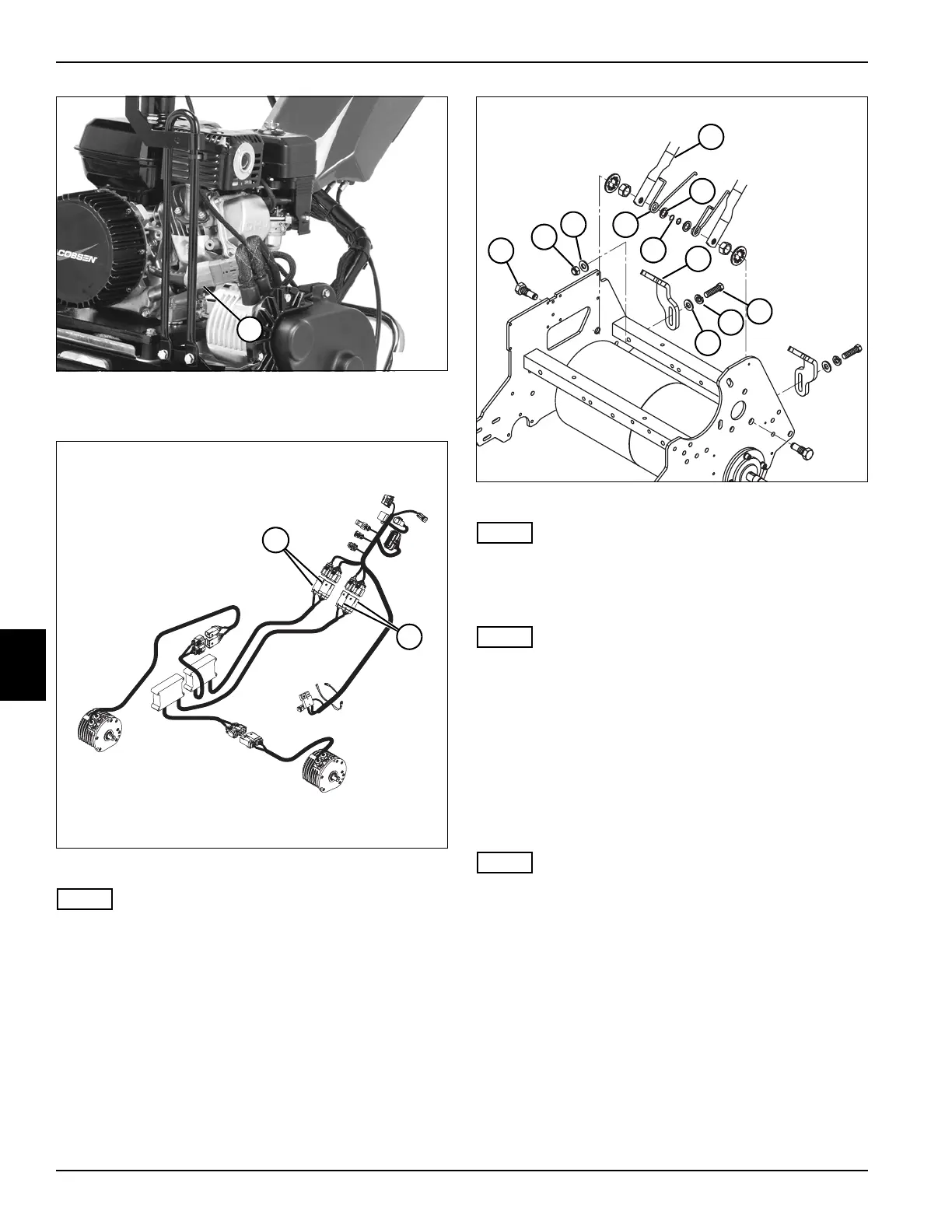
Figure 6-13
NOTE
Note orientation of torsion spring (18) before removal to
ensure correct installation.
13. Disconnect torsion spring (18) from handle stop (16).
NOTE
Support handle assembly before removing mounting
hardware.
14. Remove screw (13), lock washer (14), flat washer
(15), flat washer (19), and nut (20).
15. Remove retaining ring (17), flat washer (12), and
torsion spring (18) from handle mount bolt (21).
16. Remove handle assembly by pressing in on handle
tube (11) until end of tube clears end of handle
mount bolt (21).
NOTE
Note location and orientation of handle stop (16) before
removal to ensure correct installation.
17. Remove handle stop (16) from handle tube (11).
18. Repeat steps 13 through 17 for left side of handle
assembly.
8
TN4397
TN4430
9
10
TN4559
11
18
12
17
21
19
20
16
13
14
15