10-12 4262930-Rev A
ACCESSORIES
10
NOTE
Always use new grease seals for installation.
1. Apply a thin film of Permatex
®
Anaerobic Sealant (or
equivalent) to the outside diameter of the new grease
seals (4 and 11), and install the grease seals in the
adapter seals (5 and 12).
NOTE
Bearings and bearing cups should always be replaced as
a set.
2. If removed, press new bearing cups (1 and 8) in the
roller (7).
3. Pack the bearings (2 and 9) with grease that meets
or exceeds NLGI Grade 2 LB specifications before
installation.
4. Install the roller (7) and bearings (2 and 9) on the
roller shaft (6). Center the roller on the shaft, and
install lock nuts (3 and 10). Tighten lock nuts to
10–30 lb-ft (13.5–40.6 N·m) to seat the bearings.
5. Check the rotational resistance of the roller on the
shaft. The resistance should be 0–1 lb-in.
(0–0.11 N·m) with no end play. Adjust the lock nuts
as needed.
6. Apply a thin film of Permatex
®
Anaerobic Sealant (or
equivalent) to the outside diameter of the adapter
seals (5 and 12). Install (press) the adapter seals
(5 and 12) in the roller (7).
7. Check the rotational resistance of the roller assembly
after four revolutions. The resistance should be 6
lb-in. (0.68 N·m) maximum with no end play.
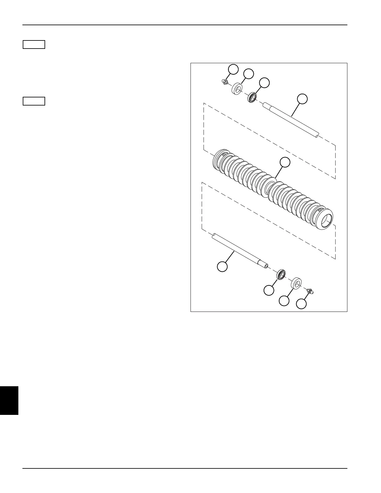
Disassembly—Grooved Disc Roller
See Figure 10-19.
Figure 10-19
1. Remove grease fittings (1 and 8) from the roller shaft
(4).
2. Support one end of the roller (5), allowing enough
free space for the seal (2) and bearing (3) to exit the
roller (5).
3. Apply pressure to the other end of the roller shaft (4)
until the seal (2) and bearing (3) are clear of the roller
(5).
4. Repeat steps 2 and 3 to remove the seal (7) and
bearing (6) from the other end of the roller (5).
TN0254
1
TN0254
2
3
4
5
4
6
8
7