ELECTRICAL
4203780 First Edition 4-83
4
10. Release the plunger to the extended position.
11. Check for continuity.
Is continuity indicated?
YES The diff lock switch is good.
NO The switch is faulty; replace the switch.
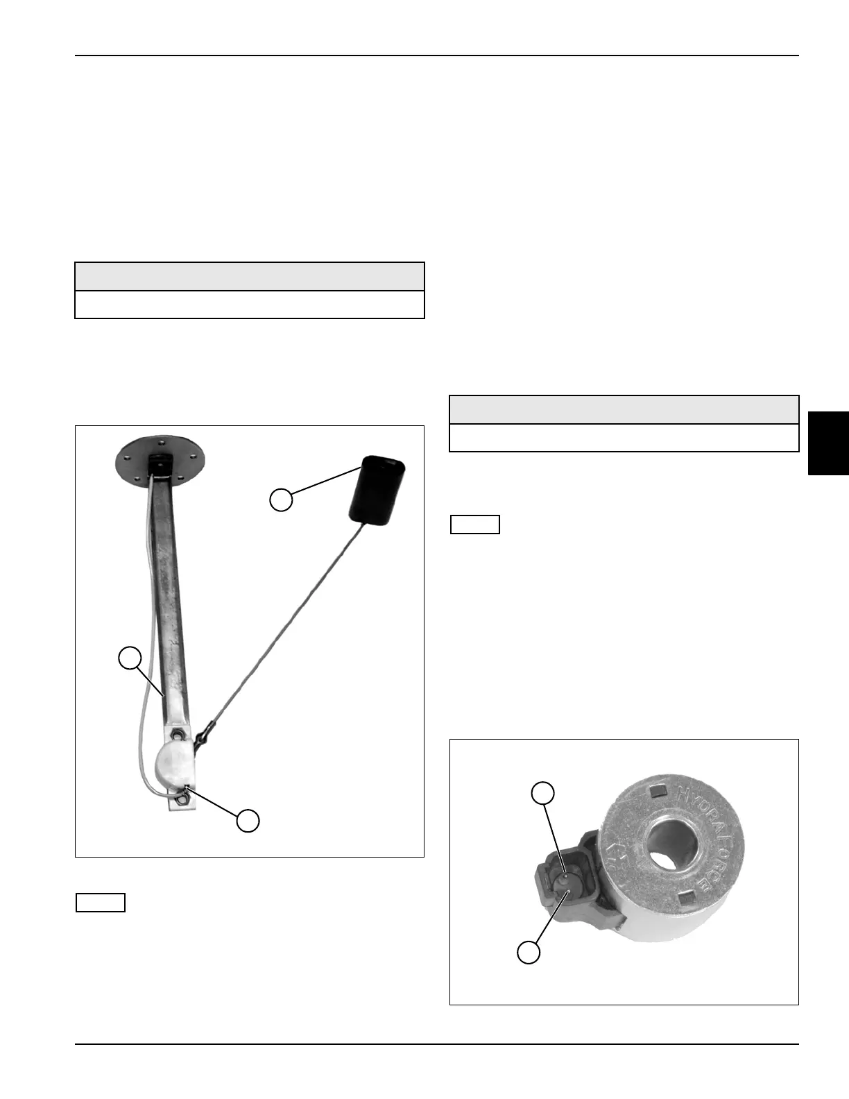
Fuel Level Sensor Test
See Figure 4-52.
1. Park the mower safely. (See “Park Mower Safely” on
page 1-6.)
2. Remove fuel level sensor. (See “Fuel Level Sensor”
on page 4-113.)
Figure 4-52
NOTE
Float shown in the full position.
3. Connect the test leads to sensor bracket (1) and
sensor terminal (3).
4. Set the meter to read ohms.
5. Move the float (2) to the full position and read the
resistance value.
Is the resistance value approximately 32 ohms?
YES Proceed to step 6.
NO The sensor is faulty; replace fuel level
sensor.
6. Move the float (2) to the empty position and read the
resistance value.
Is the resistance value approximately 256 ohms?
YES The sensor is good.
NO The sensor is faulty; replace fuel level
sensor.
Solenoids Test
See Figure 4-53.
1. Park the mower safely. (See “Park Mower Safely” on
page 1-6.)
NOTE
This procedure applies to the following solenoids:
• Front Mow Solenoid
• Right Mow Solenoid
• Left Mow Solenoid
• 4WD Solenoid
• 4WD Rev Solenoid
• Diff Lock Solenoid
2. Remove solenoid. (See “Mow Solenoids” on
page 4-105 and “4WD Solenoids” on page 4-106.)
Figure 4-53
Required Tools or Equipment
Digital Multimeter, Ohmmeter, or Continuity Tester
3
1
2
TN1889
Required Tools or Equipment
Digital Multimeter or Ohmmeter
TN1595
1
2

 Loading...


