4-96 4203780 First Edition
ELECTRICAL
4
Figure 4-88
5. Rotate indicator light holder (15) 1/8 turn
counterclockwise to disengage from socket (14).
6. Pull indicator light from indicator light holder.
Installation Note
Install the indicator light by reversing the order of
removal.
PTO Switch
Removal and Installation
See Figures 4-89 and 4-90.
1. Park the mower safely. (See “Park Mower Safely” on
page 1-6.)
2. Disconnect the battery negative (–) cable at the
battery.
3. Remove instrument panel. (See “Instrument Panel”
on page 4-110.)
Figure 4-89
Figure 4-90
NOTE
Label all wires before disconnecting to ensure correct
installation.
4. Disconnect wire connector (4).
5. Remove toggle boot (2) from PTO switch (5).
6. Remove two nuts (1), upper panel plug (3), lower
panel plug (6), and PTO switch.
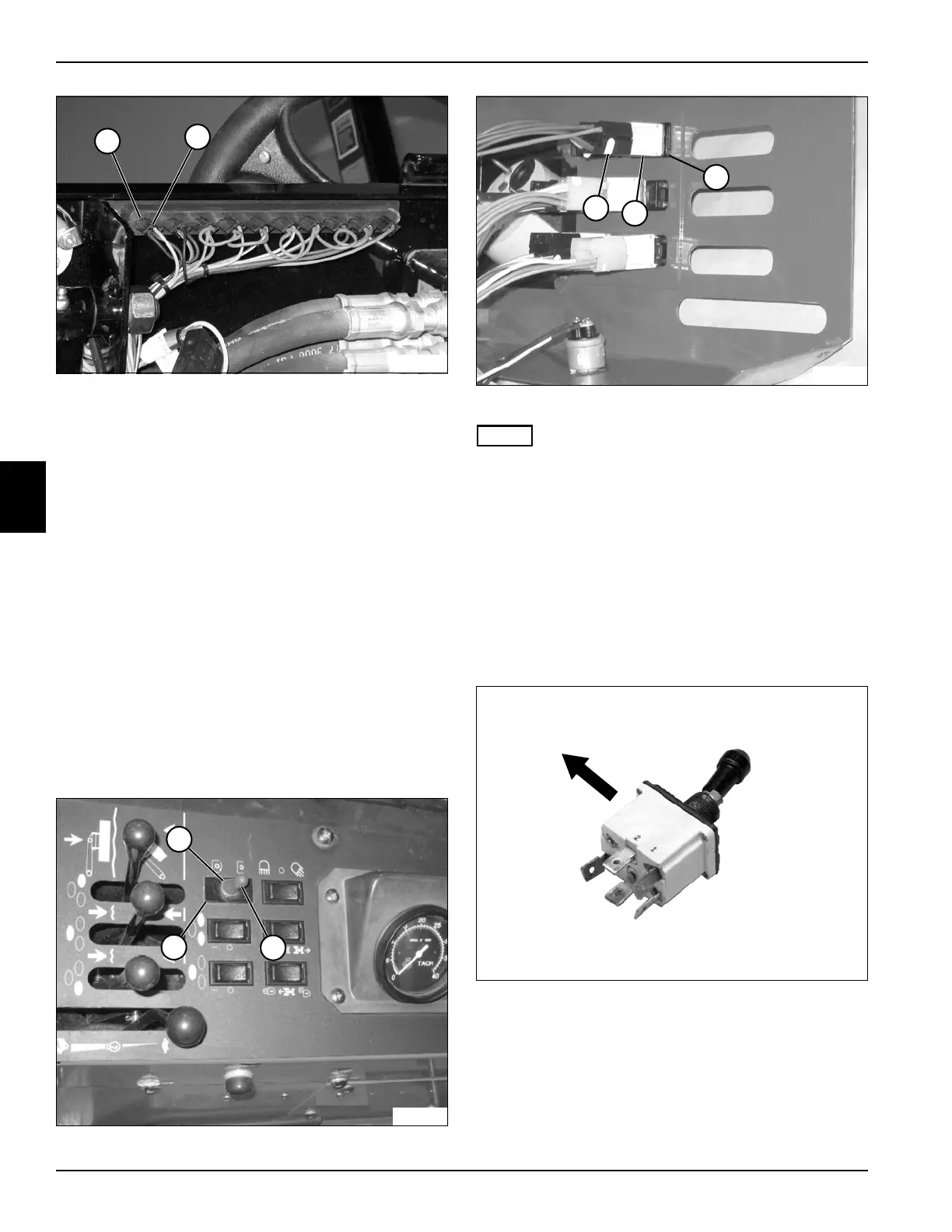
Installation Notes
• Install PTO switch by reversing the order of removal.
• See Figure 4-91.
Figure 4-91
• Arrow indicates rear of mower.
• Make sure PTO switch is installed as shown in
Figure 4-91.
8
TN2034
15
14
TN1936
2
1
3
4
5
TN1937
6
TN1969

 Loading...


