ELECTRICAL
4203780 First Edition 4-89
4
• Horn Relay (6)
• Accessory Relay (7)
NOTE
For time delay relay, (See “Time Delay Relay” on
page 4-89.)
Removal and Installation
See Figures 4-64 and 4-65.
1. Park the mower safely. (See “Park Mower Safely” on
page 1-6.)
2. Disconnect the negative (–) battery cable at the
battery.
3. Raise the seat.
Figure 4-65
4. Remove four screws (9) and cover (10).
5. Pull relay straight up and out of the relay base (8).
Installation Note
Install the relay by reversing the order of removal.
Time Delay Relay
Removal and Installation
See Figure 4-66.
1. Park the mower safely. (See “Park Mower Safely” on
page 1-6.)
2. Disconnect the negative (–) battery cable at the
battery.
3. Remove instrument panel. (See “Instrument Panel”
on page 4-110.)
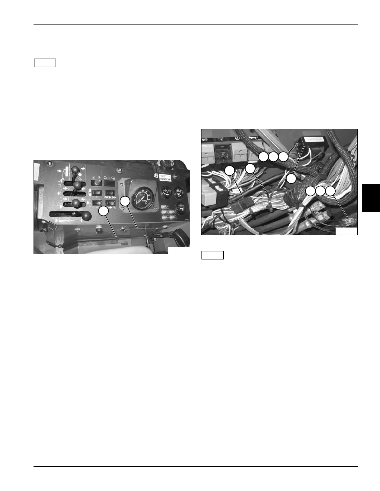
Figure 4-66
NOTE
Label all wires before disconnecting to ensure correct
installation.
4. Cut cable tie (2).
5. Disconnect wire connector (1).
6. Remove nut (7), lock washer (8), and ground wire
terminal (9).
7. Remove two nuts (3), lock washers (4), and screws
(5).
8. Remove time delay relay (6).
Installation Notes
• Install the time delay relay by reversing the order of
removal.
• Use new cable tie to secure wire connector.
TN1990
10
9
TN2031
2
3
6
1
4 5
7 8 9

 Loading...


