7-18 4203780 First Edition
STEERING
7
19. Lubricate and install the thrust bearing spacer (29)
and thrust bearing (30) into the metering ring (19).
20. Place the metering package (20—28) into the
metering ring (19), engaging the drive slot with the
steering shaft.
21. Install the commutator seal (31), seal ring (8), and
drive link (14).
22. Place the isolation manifold (13) on the metering ring
(19) with the alignment pin holes up. Install the
alignment pins (15) into the metering ring (19).
23. Install alignment pins (15) into the isolation manifold
(13).
24. Install the three springs (16) into the isolation
manifold (13) and install the valve ring (9).
25. Install the valve plate (10) as shown (closed cylinder
up) in the valve ring (9), aligning the spring slots with
the springs. Install the seal ring (18).
Figure 7-26
26. Place the three springs (17) in the port manifold (7).
27. Carefully place the port manifold (7), springs down,
onto the valve ring (9).
28. Install the O-ring (5) and seal ring (18) on the port
cover (2).
29. Install the relief valve assembly (4) in the port cover
(2).
30. Install the port manifold (7).
31. Install the nuts (1). Tighten the lock nuts gradually in
sequence to 18—22 lb-ft (24—30 N·m).
32. Install straight adapters (3) in the port cover (2).
33. Install straight adapters (12) in the isolation manifold
(13).
Steering Console
Removal and Installation
See See Figures 7-27 through 7-34.
1. Park the mower safely. (See “Park Mower Safely” on
page 1-6.)
2. Remove the steering wheel. (See “Steering Wheel”
on page 7-8.)
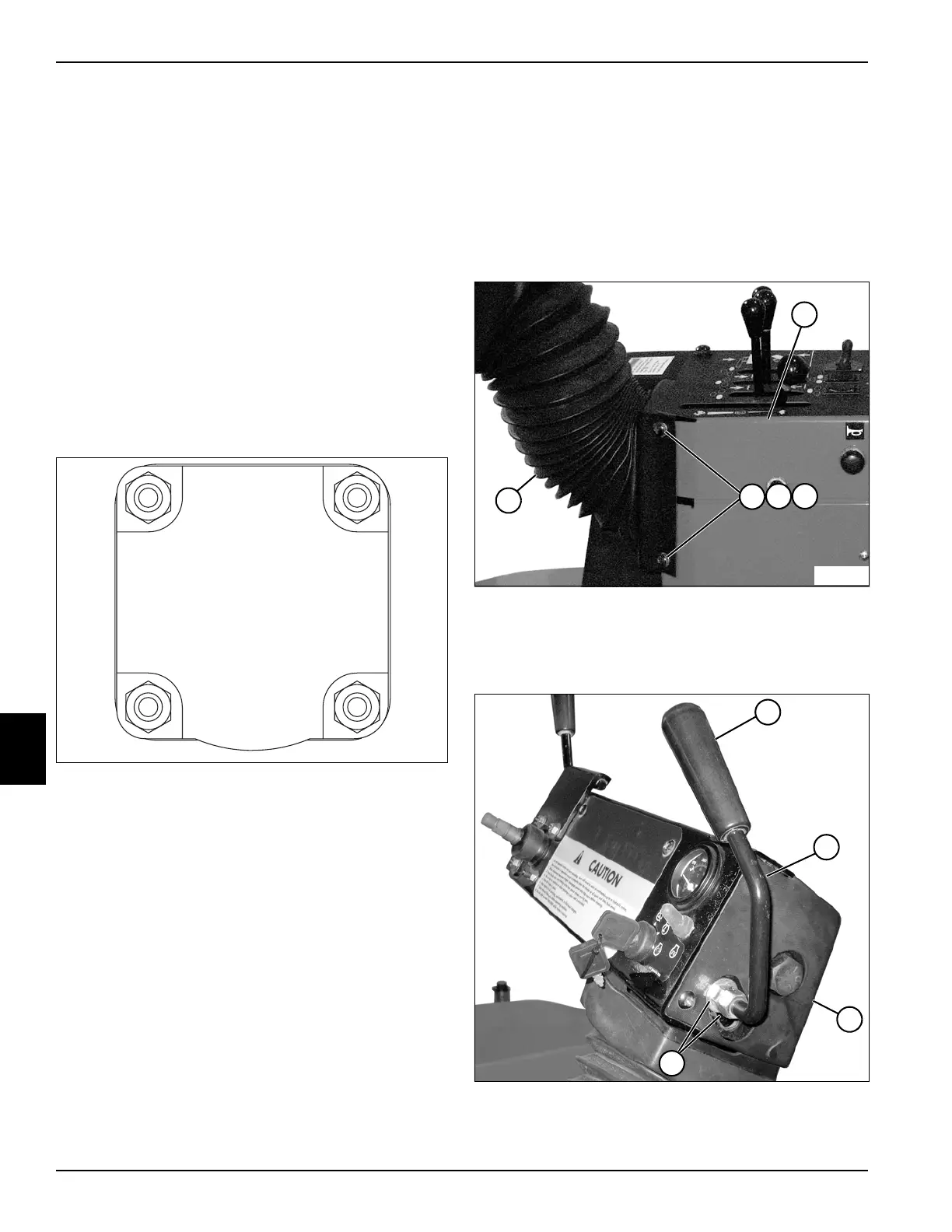
Figure 7-27
3. Remove two screws (2), lock washers (3), and flat
washers (4) from console cover assembly (5) and
console wall (1).
Figure 7-28
4. Remove (unscrew) knob (6) from tilt lever (7).
TN1884
1
2
3
4
TN1886
1
5
3
2
4
TN1738
6
7
9
8

 Loading...


