ENGINE
4203780 First Edition 3-5
3
Checks and Adjustments
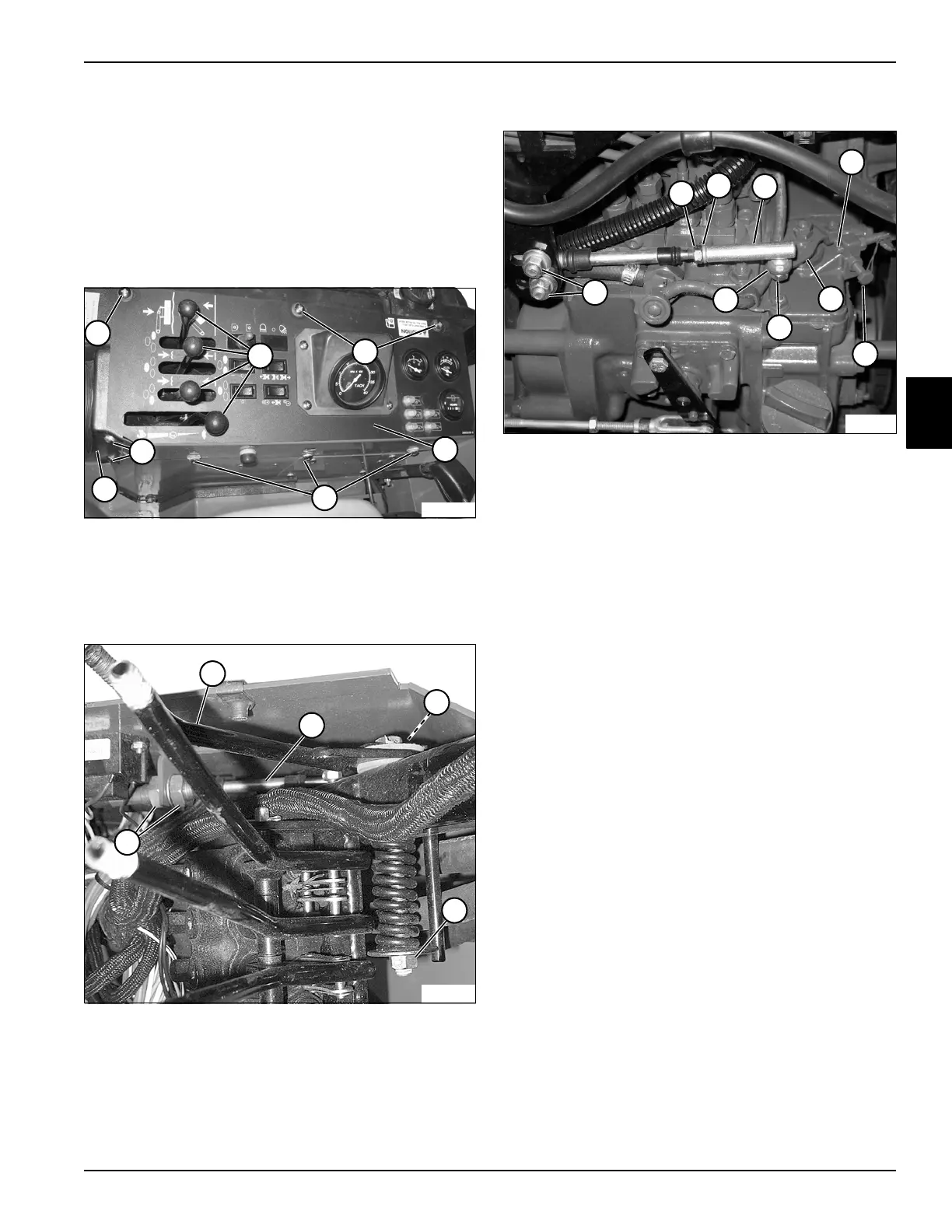
Throttle Cable
Adjustment
See Figures 3-3 through 3-5.
1. Park the mower safely. (See “Park Mower Safely” on
page 1-6.)
Figure 3-3
2. Remove four knobs (2) and eight screws (1), and
slide the console cover boot (4) back. Lift instrument
panel (3) up and turn counterclockwise to clear the
lever handles.
Figure 3-4
3. Place throttle lever (5) in slow idle position and check
throttle cable (6) and ball joint (7) for wear.
4. Check throttle for ease of movement and adjust
throttle tension with throttle tension adjuster (8).
5. Be sure throttle lock nuts (9) are tightened.
6. Move throttle lever to slow idle position.
Figure 3-5
7. Loosen clamp nuts (18) and position cable in clamp
so that governor throttle lever (15) contacts the idle
screw (14). Tighten nuts (18).
8. Push throttle lever to full open position and check to
see that governor throttle lever (15) contacts the high
speed stop (13).
9. Verify the engine rpm (idle 750–800 rpm and high
speed 2800 ± 50 rpm) at engine crankshaft using a
photo tach.
10. Adjust ball joint (12) to obtain full governor throttle
lever movement by backing off nut (10) and washer
(11) and removing nut (16) and washer (17).
Disconnect ball joint from governor lever arm and
turn clockwise or counterclockwise as needed to
adjust.
11. Assemble ball joint to governor throttle lever and
tighten hardware securely.
12. Install the instrument panel by reversing the order of
removal.
TN1990
3
4
1
1
1
1
2
6
5
8
9
TN2008
7
14
13
TN2011
15
11
10
18
17
16
12

 Loading...


