HYDROSTATIC POWER TRAIN
4203780 First Edition 5-55
5
Control Valve
Removal and Installation
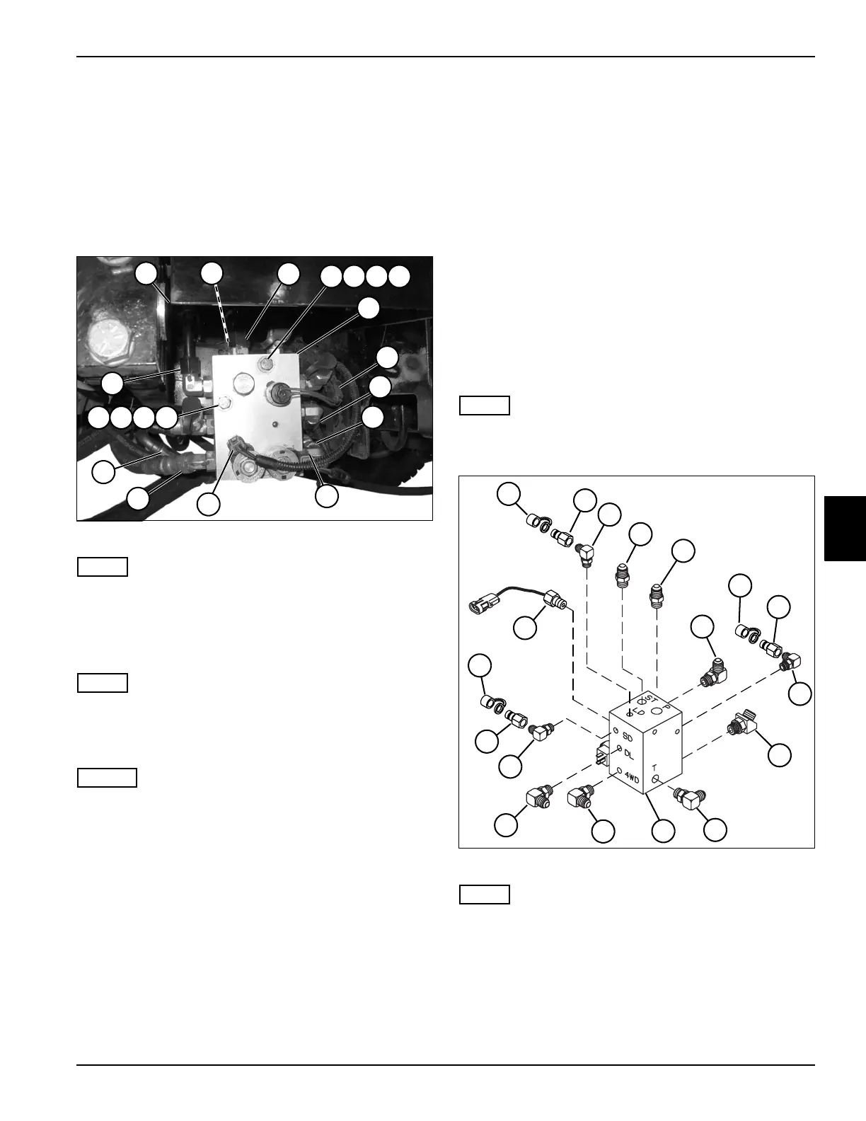
See Figure 5-52.
1. Park the mower safely. (See “Park Mower Safely” on
page 1-6.)
2. Drain hydraulic oil tank. (See “Hydraulic Oil Tank—
Drain Procedure” on page 6-58.)
Figure 5-52
NOTE
The control valve is located on the right side of machine.
3. Remove cover (1).
4. Thoroughly clean the valve, especially the area
surrounding the hydraulic hoses, tubes, and fittings.
NOTE
Label connectors before disconnecting to ensure correct
installation.
5. Disconnect electrical connectors (9, 12, and 13).
NOTES
• Label all hydraulic hoses and tubes before
disconnecting to aid in installation.
• Close all openings with caps or plugs to prevent
contamination.
6. Disconnect hydraulic hoses (2, 11, 14, and 15).
7. Disconnect hydraulic tubes (3, 10, and 16).
8. Support the control valve (8).
9. Remove mounting screws (4), washers (5), lock
washers (6), and nuts (7).
10. Remove the control valve (8).
Installation Notes
• Install the control valve by reversing the order of
removal.
• Lubricate all O-rings prior to assembly.
• Make sure new O-rings are in place before installing
hoses on fittings.
• Replace hydraulic oil filter and charge pressure filter.
• Refill hydraulic tank. (Refer to “Safety, Operation, and
Maintenance Manual” for oil specifications.)
• Start engine. Check hydraulic system for leaks.
Repair as necessary.
• Check hydraulic oil level and add if necessary.
Disassembly, Inspection, and Assembly
See Figures 5-53 and 5-54.
NOTE
Repair of the control valve is limited to replacing
cartridges or replacing O-rings on each cartridge.
Figure 5-53
NOTE
Record the location and orientation of all fittings before
removing to ensure correct installation.
1. Remove dust cover (1), diagnostic port adapter (2),
and 90° adapter (3) from port “LD.”
2. Remove straight adapter (4) from port “ST.”
3. Remove straight adapter (5) from port “P.”
4. Remove 90° adapter (6) from port “L.”
TN1921
1
16
9
13
12
14
3
10
11
8
2
15
4 5 6 7
4 5 6 7
TN1973
1
17
5
18
2
6
7
15
14
11
10
9
13
3
4
16
8
12

 Loading...


