ELECTRICAL
4203780 First Edition 4-97
4
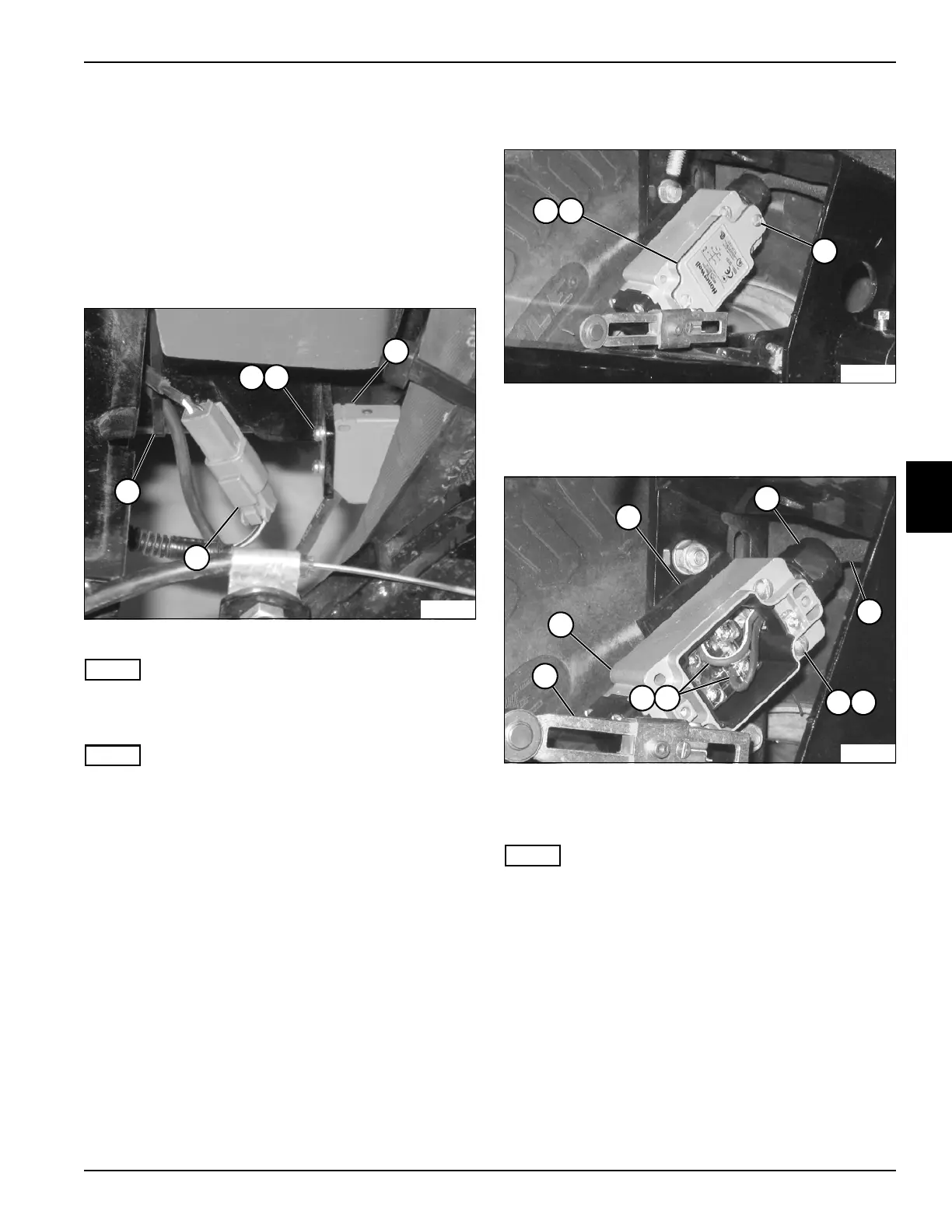
Right and Left Wing Proximity
Switches
Removal and Installation
See Figure 4-92.
1. Park the mower safely. (See “Park Mower Safely” on
page 1-6.)
2. Disconnect the negative (–) battery cable at the
battery.
Figure 4-92
NOTE
Right wing proximity switch shown; left wing is similar.
3. Cut cable tie (5).
NOTE
Label all wires before disconnecting to ensure correct
installation.
4. Disconnect wire connector (4).
5. Remove two screws (1) and flat washers (2).
6. Remove proximity switch (3).
Installation Notes
• Install the proximity switch by reversing the order of
removal.
• Use new cable tie to secure wire connector.
Front Limit Switch
Removal and Installation
See Figures 4-93 and 4-94.
1. Park the mower safely. (See “Park Mower Safely” on
page 1-6.)
2. Disconnect the negative (–) battery cable at the
battery.
Figure 4-93
3. Remove two screws (3).
4. Remove cover (1) and gasket (2).
Figure 4-94
5. Remove two screws (7), lock washers (8), and
spacer (4).
NOTE
Label all wires before disconnecting to ensure correct
installation.
6. Disconnect wires (9 and10).
7. Remove nut (5), wire harness (6), and switch (12).
Installation Notes
• Install the front limit switch by reversing the order of
removal.
• Adjust actuator arm (11) so that switch is engaged
when front lift arms are raised.
TN1976
5
3
21
4
TN1977
3
21
TN1981
8
4
5
12
6
7
109
11

 Loading...


