5-64 4203780 First Edition
HYDROSTATIC POWER TRAIN
5
Differential Lock Assembly
Disassembly, Inspection, and Assembly
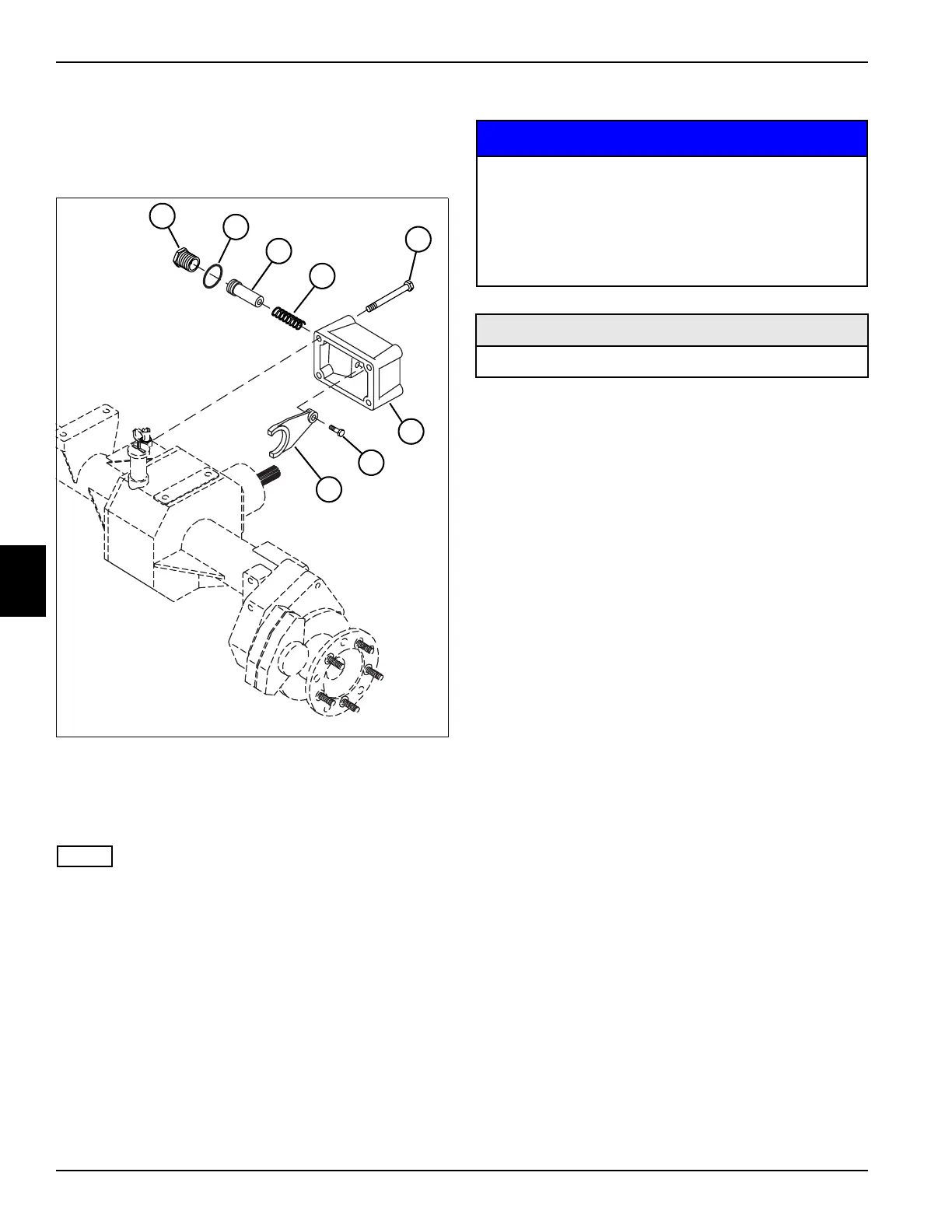
See Figure 5-68.
Figure 5-68
NOTE
If it is necessary to replace the differential lock collar, see
“Differential Assembly” on page 5-73.
1. Disassemble differential lock assembly as shown.
2. Place parts in assembly order on a clean work area
as they are removed.
Inspection Notes
• Keeping parts in assembly order, clean and air dry
each item for inspection.
• Inspect for worn or defective parts.
• Inspect all parts for cracks, nicks, burrs, and
excessive wear. Inspect for scoring, galling, and
scratches on surfaces. Replace parts as necessary.
Assembly Notes
NOTICE
• Assemble the differential lock assembly by reversing
the order of disassembly.
• Lubricate all O-rings prior to assembly.
• Apply Loctite 242 (Blue) to fork screw (7) before
assembly, and tighten to 19 lb-ft (26 N·m).
• Apply Loctite 242 (Blue) to housing screws (5) before
assembly, and tighten to 37 lb-ft (51 N·m).
1Cylinder 5Screw (4)
2 O-Ring 6 Housing
3Piston 7Screw
4Spring 8Fork
TN1907
2
6
7
8
3
4
5
1
• It is important that all parts are absolutely
clean, as contamination can result in serious
damage and/or improper operation.
• Never use shop towels or rags to dry parts
after cleaning, as lint may clog passages. Dry
parts using compressed air.
Required Materials
Loctite
®
242 (Blue)

 Loading...


