8-28 4203780 First Edition
CUTTING UNITS
8
Disassembly and Assembly
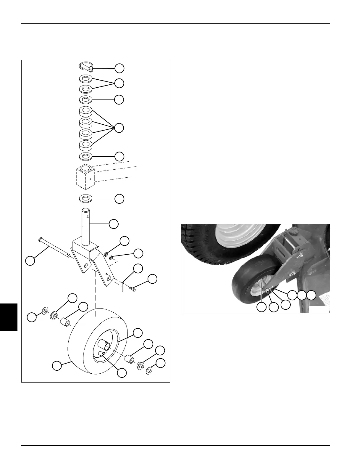
See Figure 8-20.
Figure 8-20
Disassembly Notes
• Note position and order of flat washers and
height-of-cut spacers for proper assembly.
• Inspect all moving parts for wear or damage.
Replace as necessary.
Assembly Notes
• Assemble caster wheel in reverse order of
disassembly.
• Lubricate grease fitting with grease that meets or
exceeds NLGI Grade 2 LB specifications. Apply
grease with a manual grease gun and fill slowly until
grease begins to seep out. Do not use compressed
air gun.
• Set caster tire pressure to 23 psi.
Fixed Caster Wheels
Removal and Installation
See Figure 8-21.
1. Park the mower safely. (See “Park Mower Safely” on
page 1-6.)
2. Raise and support cutting deck using jackstands.
Figure 8-21
3. Remove screw (1), lock washer (2), and nut (3).
4. Remove cotter pin (4).
5. Remove shaft pin (5) and caster wheel (6).
6. Inspect caster wheel (6) along with bearings,
bushings, washers, and pin for wear or damage.
Replace as necessary.
Installation Notes
• Inspect cotter pin for damage before installation.
• Install the fixed caster wheel by reversing the order of
removal.
1 Lock Pin 7 Lock Washer 12 Bushings
2 Flat Washer s 8 Cotter Pin 13 Washers
3 Caster Wheel Spacers 9 Screw 14 Valve Stem
4 Height-of-Cut Spacers 10 Wheel and
Bearing
15 Tire
5 Yoke 11 Rollers 16 Shaft
6Nut
TN1843
1
2
3
4
5
6
7
3
3
8
9
10
13
11
11
12
12
13
16
14
15
5
1
4
6
TN1854
2 3

 Loading...


