ACCESSORIES AND MISCELLANEOUS REPAIR
4203780 First Edition 9-17
9
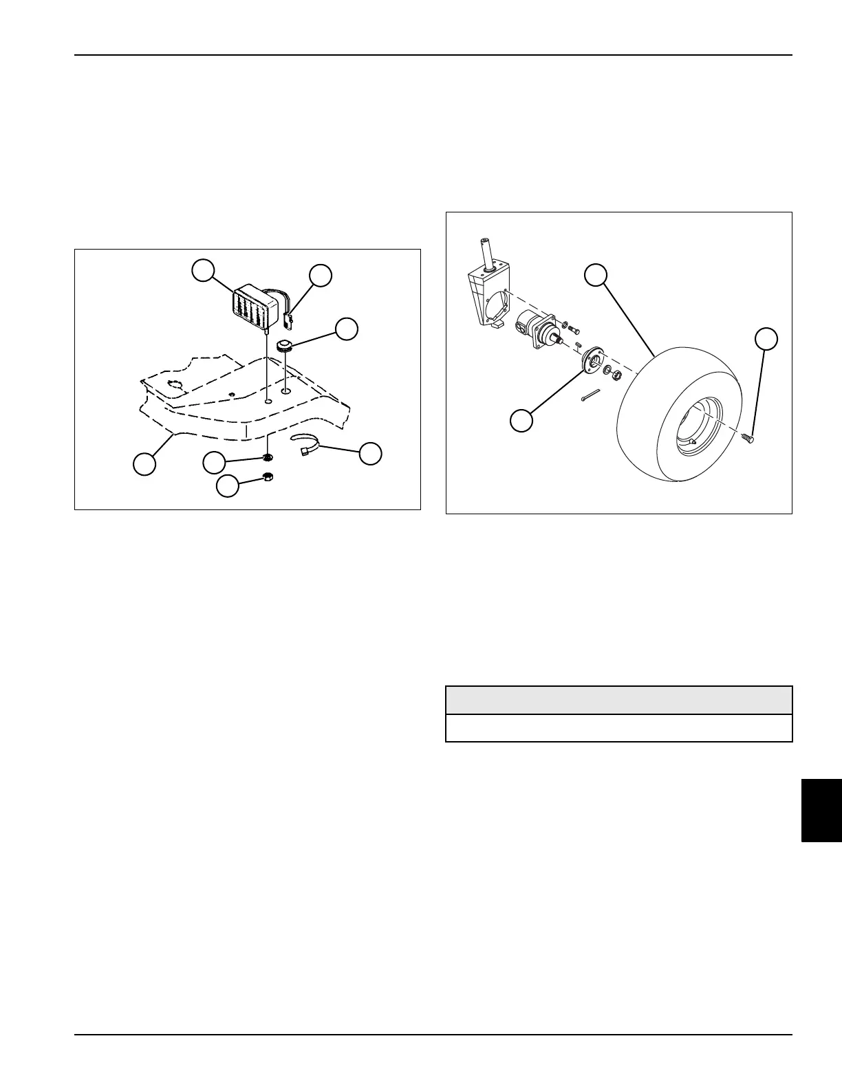
Work Light Kit
Removal and Installation
See Figure 9-24.
1. Park the mower safely. (See “Park Mower Safely” on
page 1-6.)
2. Disconnect the negative (–) battery cable at the
battery.
Figure 9-24
3. Remove grommet (3) from floorboard (7).
4. Cut cable tie (4).
5. Tag and disconnect work light wire connector (2) and
pass through floorboard.
6. Remove lock nut (5) and flat washer (6) from work
light (1).
7. Remove work light.
Installation Notes
• Install work light by reversing the order of removal.
• Use new cable tie to secure work light wire harness
connector.
• Adjust the work lights to project the desired distance
in front of the mower.
Rear Wheels
Removal and Installation
See Figure 9-25.
1. Park the mower safely. (See “Park Mower Safely” on
page 1-6.)
Figure 9-25
2. Loosen, but do not remove, wheel-to-hub lug bolts
(2).
3. Raise and support rear of mower with jackstands.
4. Remove wheel-to-hub lug bolts (2).
5. Remove wheel (1) and inspect tread area for tears or
other damage.
6. Replace tire if damage is excessive.
Installation Notes
• Inspect and clean any rust from hub (3) or wheel
mounting area. Apply anti-seize compound to lug
bolts.
• Install wheel by reversing the order of removal.
• Torque wheel-to-hub lug bolts to 40—50 lb-ft (54—68
N·m).
• Set tire pressure to 8—10 psi (0.55—0.69 bar).
T
N
1
9
1
0
1
2
3
4
6
5
7
Required Materials
Anti-Seize Compound
T
N
1
7
9
4
2
3
1

 Loading...


