9-4 4203780 First Edition
ACCESSORIES AND MISCELLANEOUS REPAIR
9
Checks and Adjustments
Park Brake Adjustment
See Figure 9-2.
1. Park the mower safely. (See “Park Mower Safely” on
page 1-6.)
2. Check linkages, cables, and pivot points to ensure
they are operating smoothly. Check brake pads for
wear.
Figure 9-2
3. To set brake force: Place brake lever in the
disengaged position. Sit in the operator’s seat and
turn knob (1) clockwise to increase force. Using a
scale to measure the amount of force, apply and
release brake every quarter turn until a force of 36—
42 lb (16—19 kg) is achieved at the base of the
adjustment knob. If a scale is not available for
measuring, place tractor in 2WD mode and adjust
brake until motor cannot overcome the park brake.
NOTES
• If the knob on the park brake has been turned to its
maximum extent, new brake pads are required.
• Brake pads must be replaced when worn to the point
that they touch each other above the brake disc.
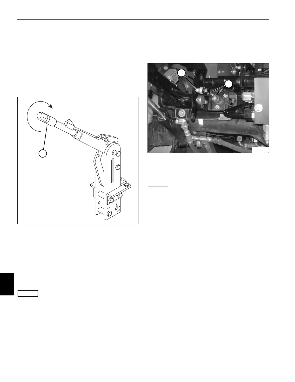
Brake Pedal Adjustment
See Figure 9-3.
1. Park the mower safely. (See “Park Mower Safely” on
page 1-6.)
S
Figure 9-3
2. Loosen nuts (2).
3. Turn ball joint (1) to adjust pedal travel.
NOTES
• Adjust ball joint so brake pedal has a minimum of
0.125 in. (3 mm) free travel before plunger touches
piston in the master cylinder.
• Turn ball joint in (clockwise) to decrease pedal travel.
• Turn ball joint out (counterclockwise) to increase
pedal travel.
4. Tighten nuts.
T
N
1
8
7
3
1
T
N
1
8
7
0
2
1

 Loading...


