ELECTRICAL
4203780 First Edition 4-5
4
Theory and Diagnostic
Information
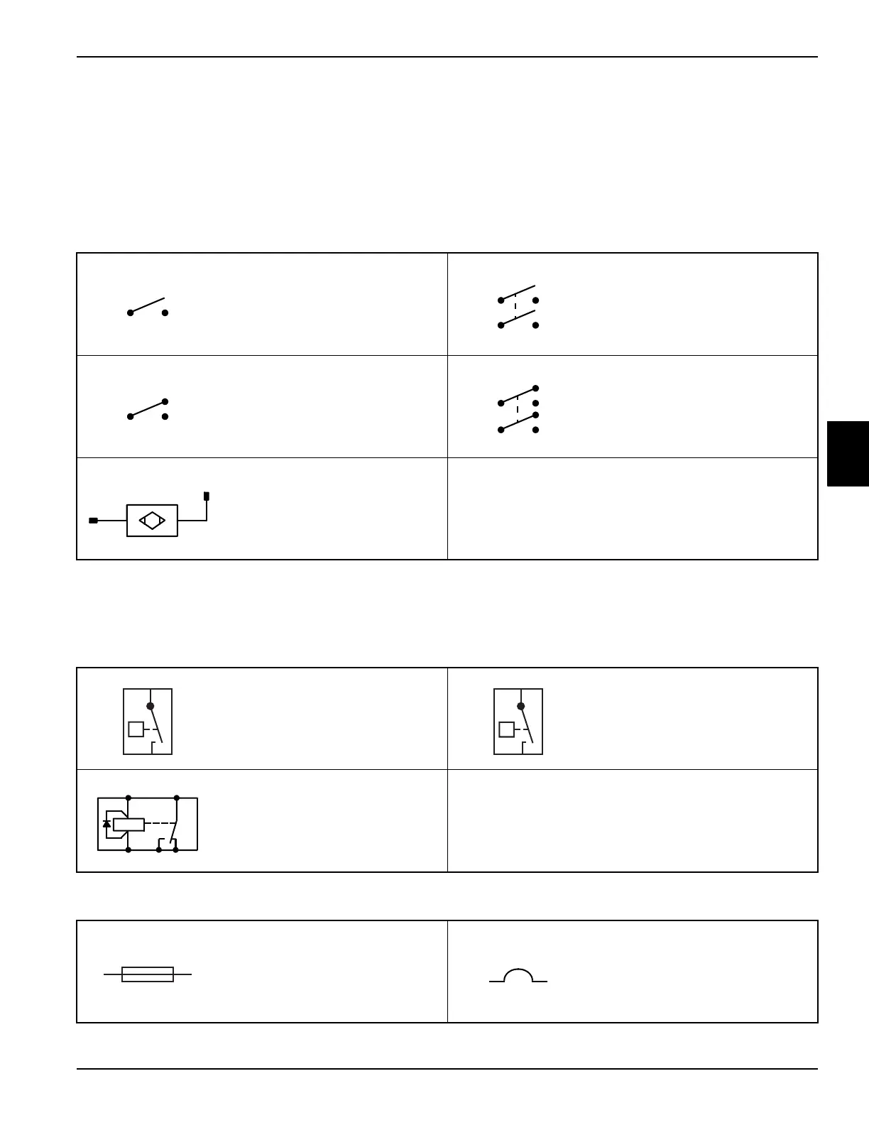
Electrical Component Symbols
The following symbols are used in the electrical
schematics to represent various electrical components.
Switches
1
1 The sample switch symbols shown are just a few of the many switch configurations. Switches are
designated by the number of “poles” (circuits controlled) and “throws” (actuator positions). Unless otherwise
specified, switches are shown in the “Normally Open” (N.O.) position.
Single Pole, Single Throw
(SPST)
Double Pole, Single Throw
(DPST)
Single Pole, Double Throw
(SPDT)
Double Pole, Double Throw
(DPDT)
Proximity Switch
Switching Devices
Temperature Switch Pressure Switch
Relay
Circuit Protection Devices
Fuse Circuit Breaker
N.O.
Blk Wht
(+)
t˚
P
87 87A85
86 30

 Loading...


