4-110 4203780 First Edition
ELECTRICAL
4
Instrument Panel
Removal and Installation
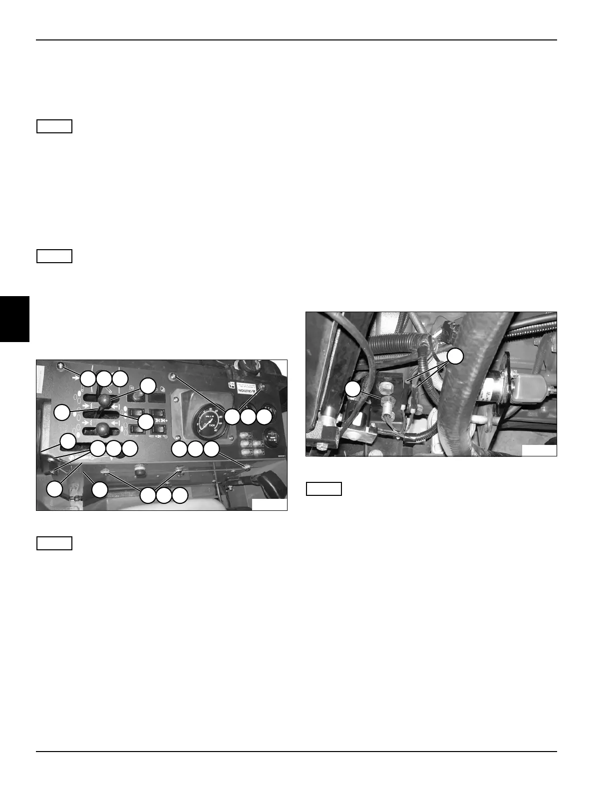
See Figure 4-124.
NOTE
If servicing individual components, it is not necessary to
completely remove the instrument panel. In most cases,
the instrument panel can be moved aside for access to
components.
1. Park the mower safely. (See “Park Mower Safely” on
page 1-6.)
2. Remove horn/test switch. (See “Horn/Test Switch” on
page 4-92.)
NOTE
Label all wires before disconnecting to ensure correct
installation.
3. Disconnect the negative (–) battery cable at the
battery.
4. If removing the instrument panel, disconnect the
positive (+) battery cables from the battery.
Figure 4-124
NOTE
If moving the instrument panel aside, use caution to
prevent stretching or kinking of the wires.
5. Remove four threaded knobs (4).
6. Remove six screws (1), lock washers (2), and flat
washers (3).
7. Remove two screws (8), lock washers (9), and flat
washers (10).
8. Slide steering console cover (11) away from
instrument panel (7).
9. Lift the instrument panel (7) to clear the edge of the
console wall (6) and rotate the instrument panel to
diagonally align the four levers (12) with the four slots
(5) in the instrument panel.
10. Lift and move the instrument panel aside or service
components as needed.
Installation Notes
• Anti-seize must be applied to screw threads when
installing instrument panel.
• Install the instrument panel by reversing the order of
removal.
Engine Speed Sensor
Removal and Installation
See Figure 4-125.
1. Park the mower safely. (See “Park Mower Safely” on
page 1-6.)
2. Raise the hood.
3. Disconnect the negative (–) battery cable at the
battery.
Figure 4-125
NOTE
Label all wires before disconnecting to ensure correct
installation.
4. Disconnect the engine speed sensor connectors (2).
5. Remove engine speed sensor (1).
Installation Note
Install the engine speed sensor by reversing the order of
removal.
TN1990
12
1 2
11
4
3
1 2 3
1 2 3
8 9 10
1 2 3
7
6
5
TN1972
1
2

 Loading...


