HYDROSTATIC POWER TRAIN
4203780 First Edition 5-69
5
Drive Axle Reducer Assembly
Removal
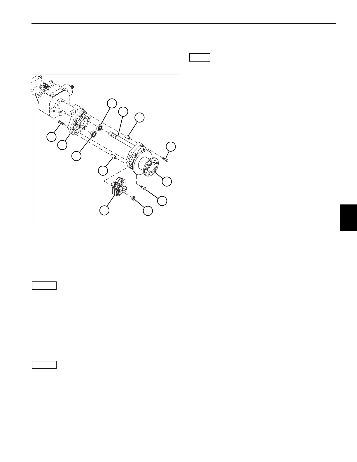
See Figure 5-72.
Figure 5-72
NOTES
• Left side shown.
• Step 1 applies to the right side only.
1. Remove the differential lock assembly. (See
“Differential Lock Assembly” on page 5-64.)
2. Place a suitable container under the reduction
assembly to catch oil.
3. Remove two nuts (7) and screws (11), and remove
the brake caliper assembly (8).
NOTES
• Remove the reducer shaft (2) only as needed.
• When removing the right reducer shaft, the
differential lock collar will slide off the reducer shaft.
4. Remove four screws (4 and 6), and remove the
reducer assembly (5) from the differential
housing (10).
5. Remove two dowel sleeves (3) from the differential
housing (10).
NOTE
The bearings are press-fit in the differential housing.
Remove the bearings only if replacement is required.
6. Remove the drive axle (1) and wheel axle (9)
bearings from the differential housing (10).
1 Bearing, Drive Axle 7 Nut (2)
2 Reducer Shaft 8 Brake Caliper Assembly
3 Dowel Sleeve (2) 9 Bearing, Wheel Axle
4 Screw (2) 10 Differential Housing
5 Drive Axle Reducer Assembly, Left 11 Screw (2)
6Screw (2)
TN1920
3
4
6
8
11
10
7
9
1
5
3
2

 Loading...


