ELECTRICAL
4203780 First Edition 4-95
4
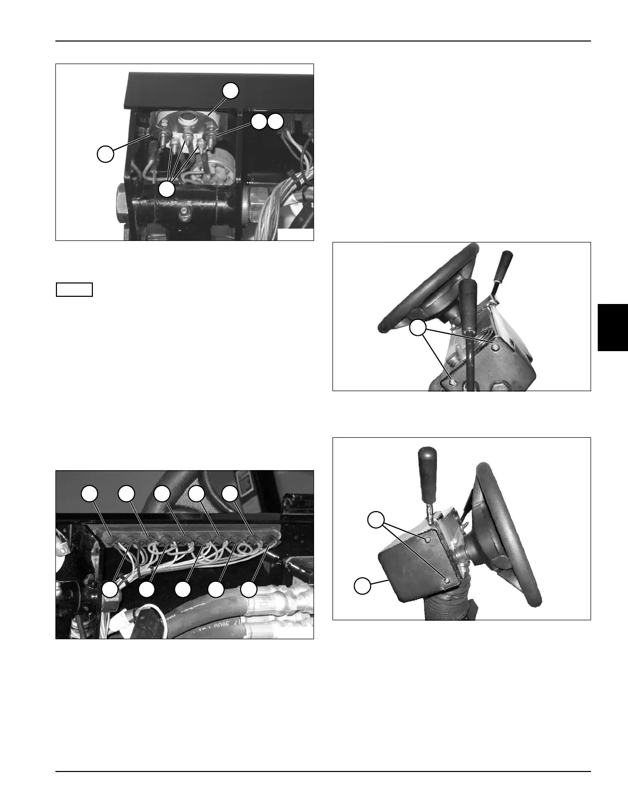
Figure 4-84
5. Remove nuts (5), lock washers (6), and bracket (8).
NOTE
Label all wires before disconnecting to ensure correct
installation.
6. Disconnect wire terminals (7).
7. Remove engine temperature gauge (4).
Installation Note
Install the engine temperature gauge by reversing the
order of removal.
Indicator Lights
See Figure 4-85.
Figure 4-85
This procedure applies to the following indicator lights:
• Right Turn Indicator (1)
• Glow Plug Light (10)
• Air Filter Service Light (2)
• Return Filter Service Light (9)
• Hyd Oil Temp Light (3)
• Charge Filter Service Light (8)
• Low Charge Pressure Light (4)
• Engine Coolant Temp Light (7)
• Engine Oil Pressure Light (5)
• Left Turn Indicator (6)
Removal and Installation
See Figures 4-86 through 4-88.
1. Park the mower safely. (See “Park Mower Safely” on
page 1-6.)
2. Disconnect the negative (–) battery cable at the
battery.
Figure 4-86
3. Remove right cover screws (11).
Figure 4-87
4. Remove left cover screws (12) and pull down cover
(13).
8
TN2033
4
5
7
6
TN2034
1 2 3 4 5
10 89 7 6
TN1903
11
TN1904
12
13

 Loading...


