ELECTRICAL
4203780 First Edition 4-93
4
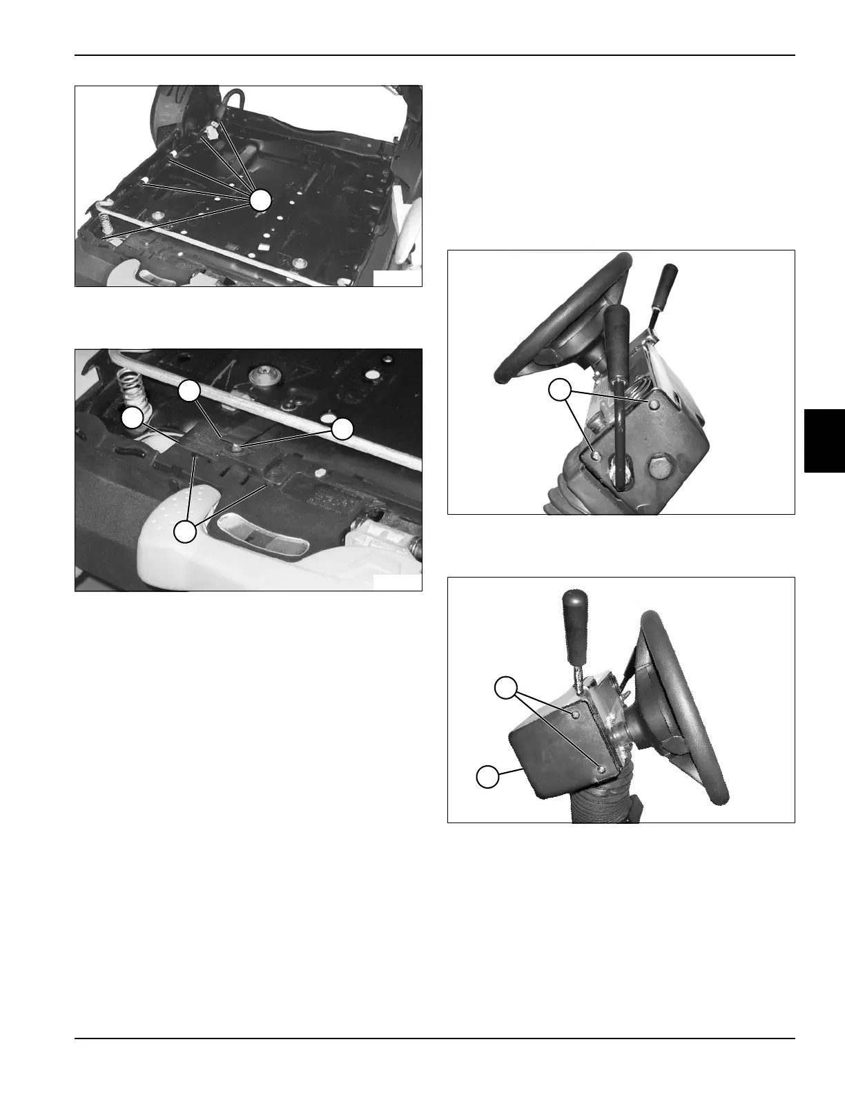
Figure 4-76
10. Cut cable ties (8).
Figure 4-77
11. Disengage switch cover tabs (12) and remove switch
cover (9).
12. Raise end of switch actuator (10) and remove seat
switch (11).
Installation Notes
• Install the seat switch by reversing the order of
removal.
• Use new cable ties to secure wire harness and wire
connector.
Glow Plug Switch
Removal and Installation
See Figures 4-78 through 4-81.
1. Park the mower safely. (See “Park Mower Safely” on
page 1-6.)
2. Disconnect the negative (–) battery cable at the
battery.
Figure 4-78
3. Remove right cover screws (1).
Figure 4-79
4. Remove left cover screws (2) and pull down cover
(3).
TN1988
8
TN1989
12
9
11
10
TN1903
1
TN1904
2
3

 Loading...


