5-70 4203780 First Edition
HYDROSTATIC POWER TRAIN
5
Disassembly and Inspection
See Figure 5-73.
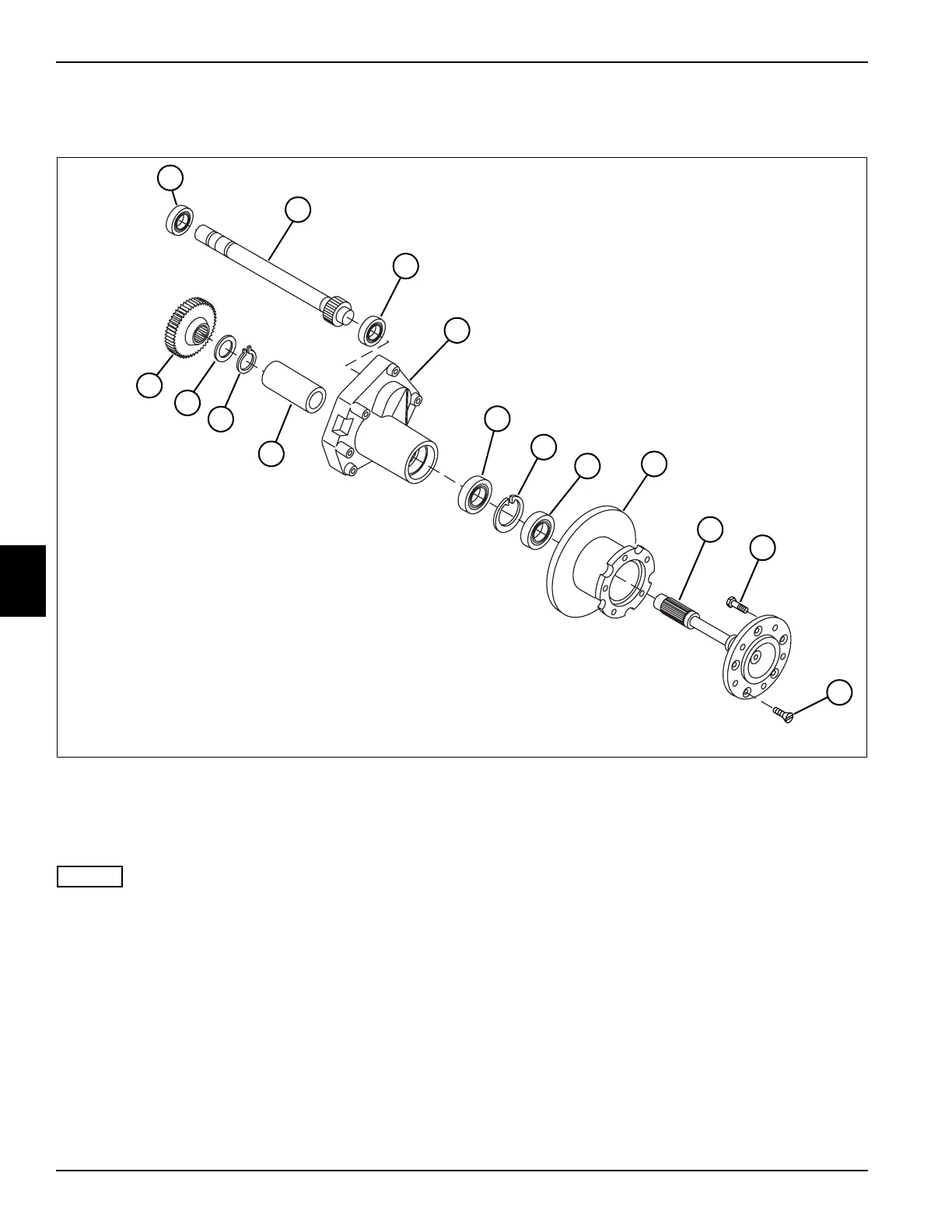
Figure 5-73
NOTES
• Left side shown.
• Remove wheel bolts (9) only if replacement is
required.
1. Disassemble drive axle reducer as shown.
2. Place parts in assembly order on a clean work area
as they are removed.
Inspection Notes
• Keeping parts in assembly order, clean and air dry
each item for inspection.
• Inspect for worn or defective parts.
• Inspect all parts for cracks, nicks, burrs, and
excessive wear. Inspect for scoring, galling, and
scratches on surfaces. Replace parts as necessary.
1 Ball Bearing (2 per side) 5 Retaining Ring 9 Wheel Bolt (5 per side) 13 Washer
2 Reducer Shaft 6 Seal 10 Flat Head Screw (5 per side) 14 Gear, Reducer
3 Housing, Reducer 7 Brake Disk 11 Spacer, Tube
4 Ball Bearing 8 Drive Axle 12 Retaining Ring
TN1786
2
1
1
7
9
3
4
6
14
13
8
12
10
11
5

 Loading...


