HYDROSTATIC POWER TRAIN
4203780 First Edition 5-71
5
Installation
See Figures 5-74 through 5-79.
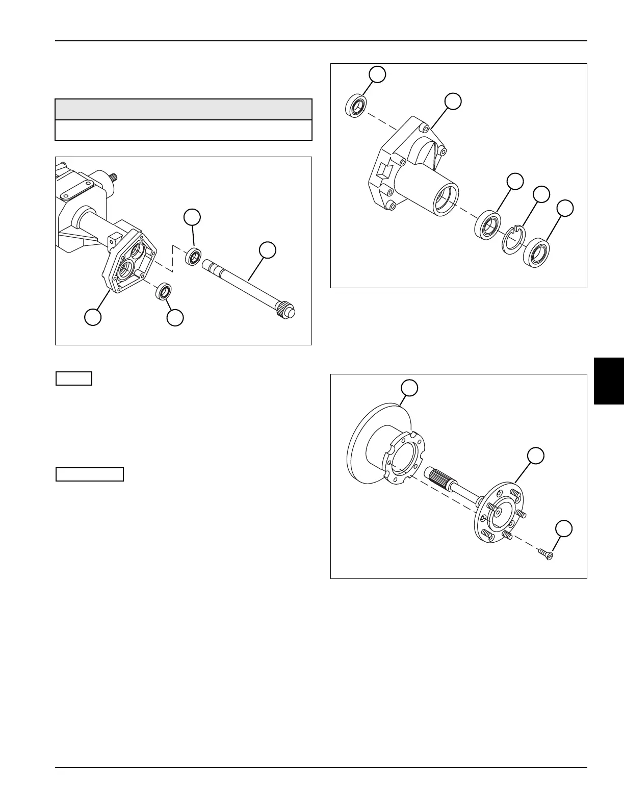
Figure 5-74
NOTE
If the axle shafts were not removed, proceed to step 7.
1. Press the wheel axle bearing (3) into the differential
housing (4).
2. Support the inner race of the drive axle bearing (1),
and press the reducer shaft (2) into the bearing.
IMPORTANT
Steps 3 through 5 apply to the right side only. If
installing the left side axle, proceed to step 6.
3. Remove the differential lock assembly. (See
“Differential Lock Assembly” on page 5-64.)
4. Press the reducer shaft (2)/bearing (1) assembly into
the differential housing (4), sliding the reducer shaft
through the differential lock collar.
5. Install the differential lock assembly. (See
“Differential Lock Assembly” on page 5-64.)
6. Press the reducer shaft (2)/bearing (1) assembly into
the differential housing (4).
Figure 5-75
7. Press ball bearings (5 and 7) into the reducer
housing (6).
8. Install retaining ring (8) and seal (9) into the reducer
housing (6).
Figure 5-76
9. Install drive axle (11) to brake disk (10) using five flat
head screws (12). Tighten screws to 29 lb-ft
(40 N·m).
Required Materials
Loctite
®
Ultra-Blue Gasket Material
TN1924
4
3
2
1
TN1923
9
8
7
5
6
TN1925
12
11
10

 Loading...


