HYDROSTATIC POWER TRAIN
4203780 First Edition 5-59
5
Disassembly, Inspection, and Assembly
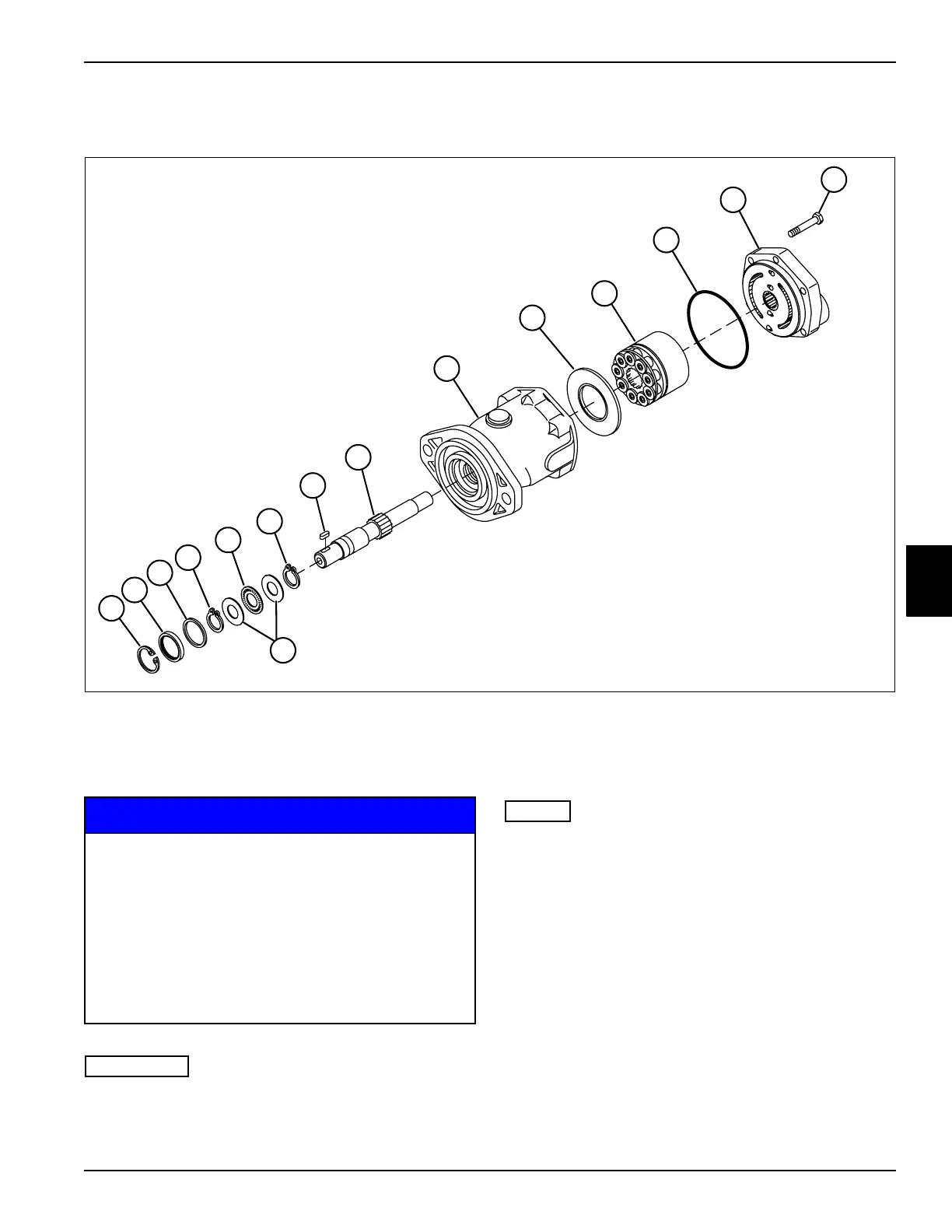
See Figure 5-56.
Figure 5-56
NOTICE
IMPORTANT
Do not disassemble the rotating assembly (10). If
parts are worn or damaged, replace the entire
rotating assembly.
NOTES
• The drive shaft (7) is press-fit into a bearing in the
housing (8). Do not remove the shaft unless the
bearing or drive shaft is worn or damaged.
• If the drive shaft (7) must be removed, press the drive
shaft out from the inside of the housing (8).
• If bearing replacement is required, the entire housing
(8) must be replaced.
1. Disassemble front wheel motor as shown.
2. Place parts in assembly order on a clean work area
as they are removed.
1 Retaining Ring 5 Thrust Bearing 9 Cam Plate Insert 13 Screw (6)
2 Shaft Seal 6 Key 10 Rotating Assembly 14 Thrust Race (2)
3 Washer 7 Drive Shaft 11 O-Ring
4 Retaining Ring (2) 8 Housing 12 Backplate Assembly
TN1902
TN1902
6
4
2
11
12
13
1
9
10
14
4
7
3
5
8
• It is important that motor parts are marked
and placed in assembly order to aid in
assembly.
• It is important that all motor parts are
absolutely clean, as contamination can result
in serious damage and/or improper operation.
• Never use shop towels or rags to dry parts
after cleaning, as lint may clog passages. Dry
parts using compressed air.

 Loading...


