4-14
dummyheaddummyhead
TROUBLESHOOTING
MIL AND WARNING BUZZER DOES
NOT OPERATE
1. Fuse inspection
Turn the combination switch OFF.
Check for blown No.2, No.6, and No.5 fuses.
Is the fuse blown?
YES – Replace the blown fuse and check for
short in the main wire harness or incorrect
load by referring to the "FUSE LOAD
CHART."(page 4-13)
NO – GO TO STEP 2.
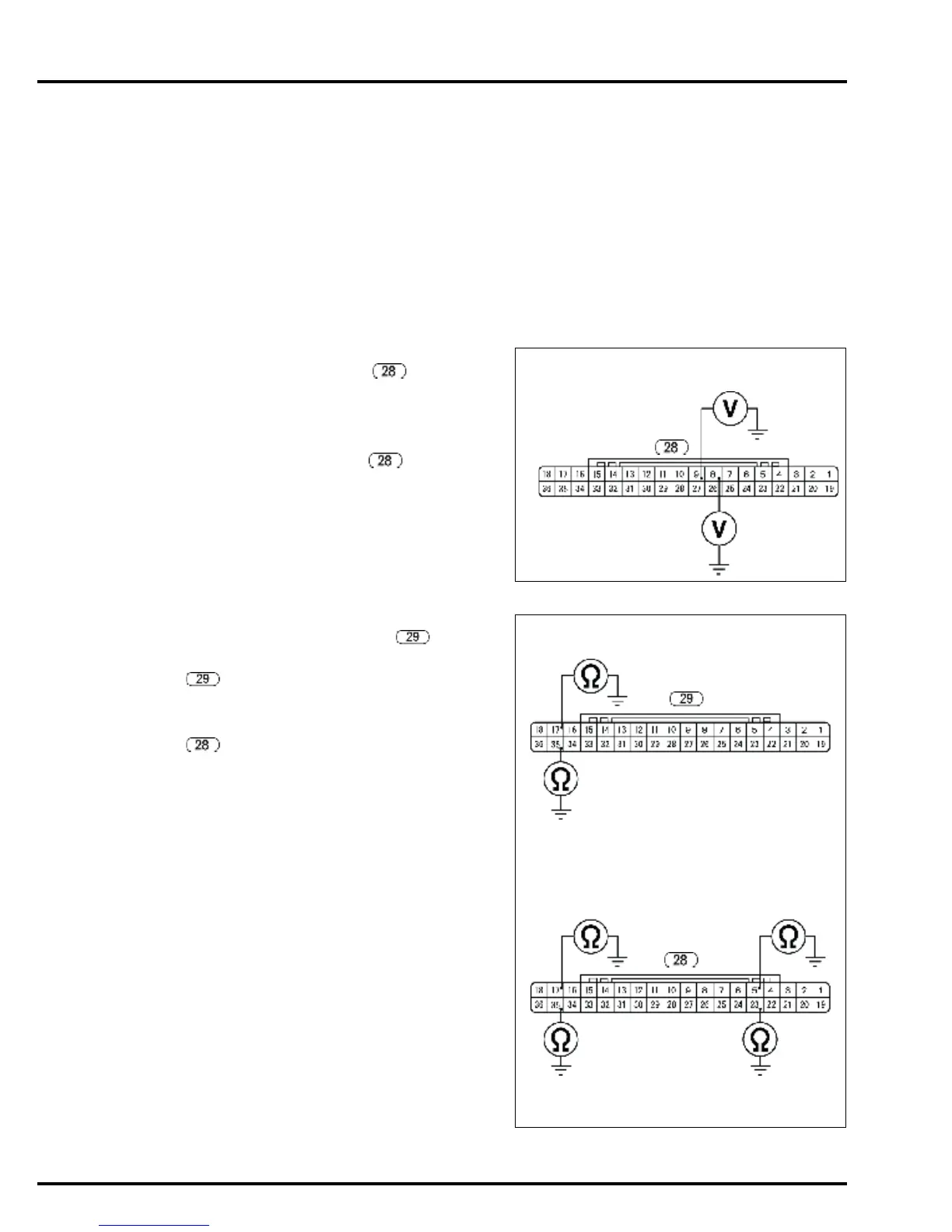
2. ECM power line inspection
Turn the combination switch OFF.
Disconnect ECM connector B .
Turn the combination switch ON.
Measure the battery voltage between the respective
terminals of the main wire harness side No.8
(Yellow/Black) terminal and No.9 (Yellow/Black)
terminal of ECM connector B and the engine
ground.
Does battery voltage exist?
YES – GO TO STEP 3.
NO – GO TO STEP 4.
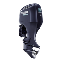
3. ECM ground line inspection
Turn the combination switch OFF.
Disconnect the ECM connector A .
Check for continuity between the ECM connector A
main wire harness side No.17 (Green)
terminal, No.35 (Green) terminal and engine
ground.
Check for continuity between the ECM connector B
main wire harness side No.5 (Blue) terminal,
No.17 (Green) terminal, No.23 (Blue) terminal,
No.35 (Green) terminal and engine ground.
Is there continuity?
YES – Replace the ECM with a new one and
recheck.
NO – Repair open in the wire harness between
the ECM and engine ground.
IGP2
(Yellow/Black)
IGP1
(Yellow/Black)
ECM CONNECTOR B
MAIN WIRE HARNESS SIDE
ECM CONNECTOR A
MAIN WIRE HARNESS SIDE
PG3
(Green)
PG4
(Green)
PG1
(Green)
PG2
(Green)
LG2
(Blue)
LG1
(Blue)
ECM CONNECTOR B
MAIN WIRE HARNESS SIDE