4-15
dummyheaddummyhead
TROUBLESHOOTING
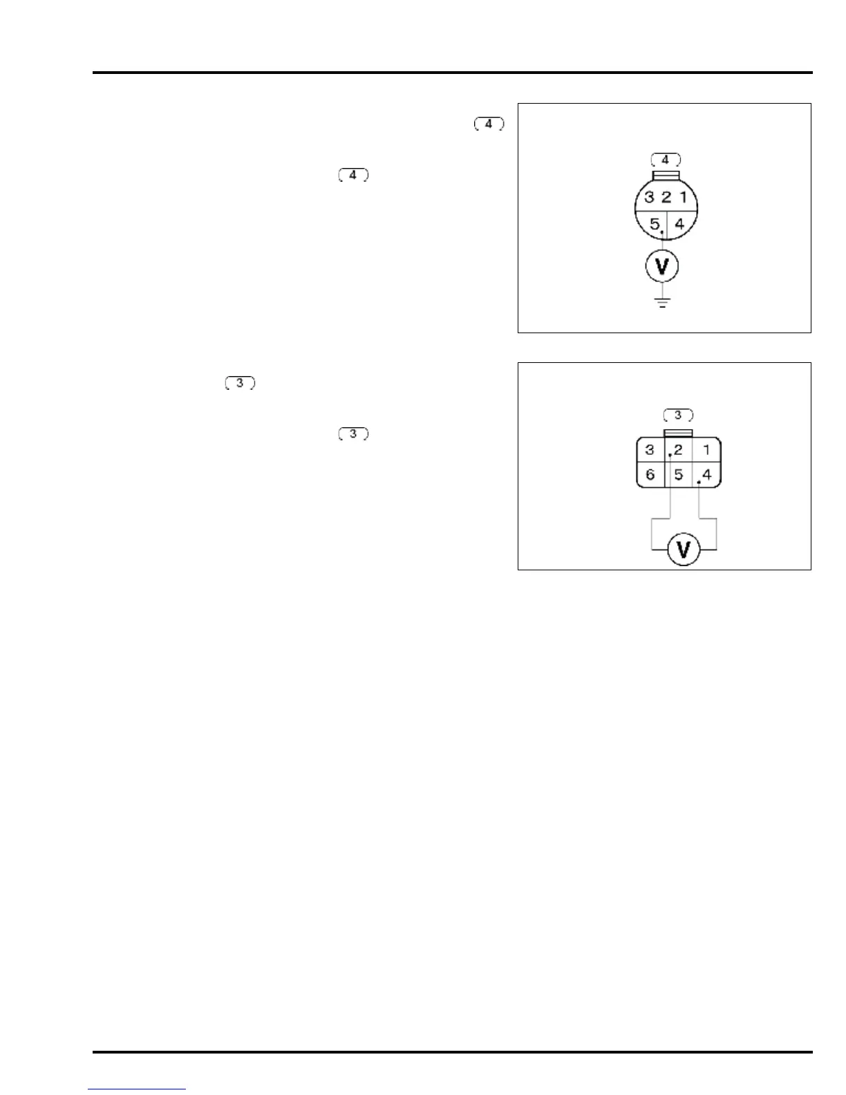
4. No.6 fuse line inspection
Turn the combination switch OFF.
Disconnect PGM-FI/main relay 5P connector .
Turn the combination switch ON.
Measure the voltage between the PGM-FI/main
relay 5P connector main wire harness side
No.5 (White) terminal and engine ground.
Does battery voltage exist?
YES – GO TO STEP 5.
NO – Repair open in the wire harness between
the battery and PGM-FI/main relay.
5. No.2 fuse line inspection
Disconnect the PGM-FI/main relay 6P connector
.
Turn the combination switch ON.
Measure the voltage between the PGM-FI/main
relay 6P connector main wire harness side
No.2 (Black/Yellow) terminal and No.4 (Black)
terminal.
Does battery voltage exist?
YES – GO TO STEP 6.
NO – • Repair open in the wire harness
between the battery and combination
switch
• Repair open in the wire harness
between the combination switch and
PGM-FI/main relay
• Faulty combination switch
6. Main relay inspection
Turn the combination switch OFF.
Remove the PGM-FI/main relay (page 10-3).
Inspect the PGM-FI/main relay (page 10-13).
Is PGM-FI/main relay normal?
YES – • Repair open in the wire harness
between the ECM and PGM-FI/main
relay.
• Replace the ECM with a new one and
recheck.
NO – Replace the PGM-FI/main relay with a new
one and recheck.
+B
(White)
PGM-FI/MAIN RELAY 4P CONNECTOR
MAIN WIRE HARNESS SIDE
GND
(Black)
LOAD SIGNAL
(Black/yellow)
PGM-FI/MAIN RELAY 6P CONNECTOR
MAIN WIRE HARNESS SIDE