5-62
dummyheaddummyhead
FUEL SYSTEM
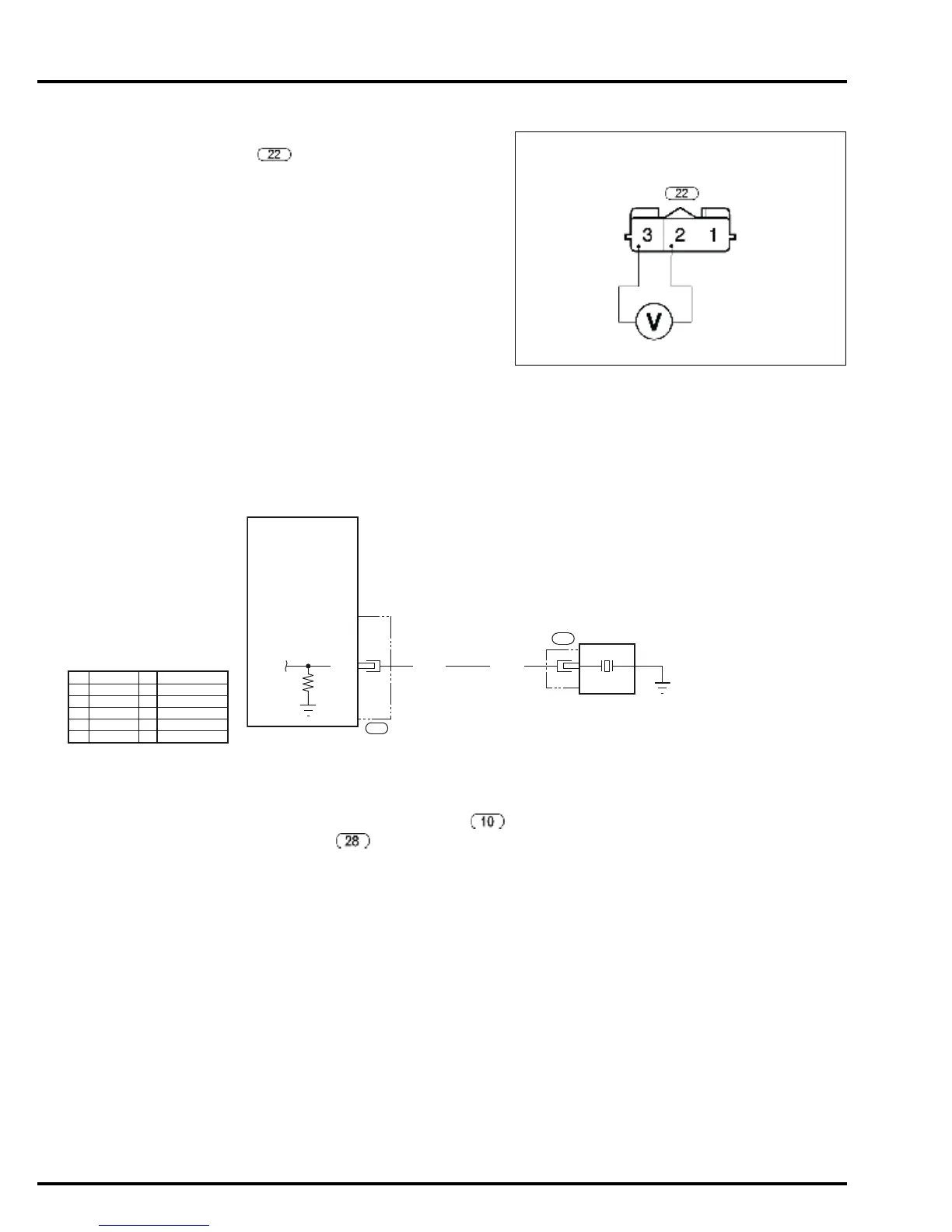
3. EOP sensor signal line open or short circuit/
GND line open circuit inspection
Measure the voltage between the EOP sensor 3P
connector main wire harness side No.2
(Yellow/Red) terminal and No.3 (Green) terminal.
Is the measurement within 4.75 – 5.25 V?
YES – Replace the EOP sensor with a new one
and recheck.
NO – • Repair open or short in the Yellow/Red
wire
• Repair open in the Green wire.
• If the main wire harness is normal,
replace the ECM with a new one, and
recheck.
MIL BLINKS 23 (2 LONG BLINKS AND 3 SHORT BLINKS)
KNOCK SENSOR
1. Symptom reproduction test
Turn the combination switch OFF.
Disconnect the knock sensor 1P connector
and ECM connector B , and then reconnect
them.
Clear the DTC (page 5-5).
Start the engine and let it run at 5,000 min
-1
(rpm) for
7 minutes or more under no load.
Increase the engine speed gradually and run it at
3,000 min
-1
(rpm) for 10 seconds.
Turn the combination switch OFF and connect the
SCS service check connector.
Turn the combination switch ON and check the
number of blinks of the MIL.
Does the MIL blink 23?
YES – GO TO STEP 2.
NO – Temporary failure (code does not
reappear)
EOP SENSOR 3P CONNECTOR
MAIN WIRE HARNESS SIDE
POIL
(Yellow/Red)
SG2
(Green)
R/Bu
29
ECM
KS
28
KNOCK
SENSOR
R/Bu
1
10
BLACK
YELLOW
BLUE
GREEN
RED
WHITE
BROWN
ORANGE
LIGHT BLUE
LIGHT GREEN
PINK
GRAY
Bl
Y
Bu
G
R
W
Br
O
Lb
Lg
P
Gr
 Loading...