0-6
dummyheaddummyhead
How to use this manual
HOW TO READ A WIRING DIAGRAM & RELATED INFORMATION
The wiring diagram, connector general layout drawing, connector drawings, and the symbols used in troubleshooting are explained
in this section.
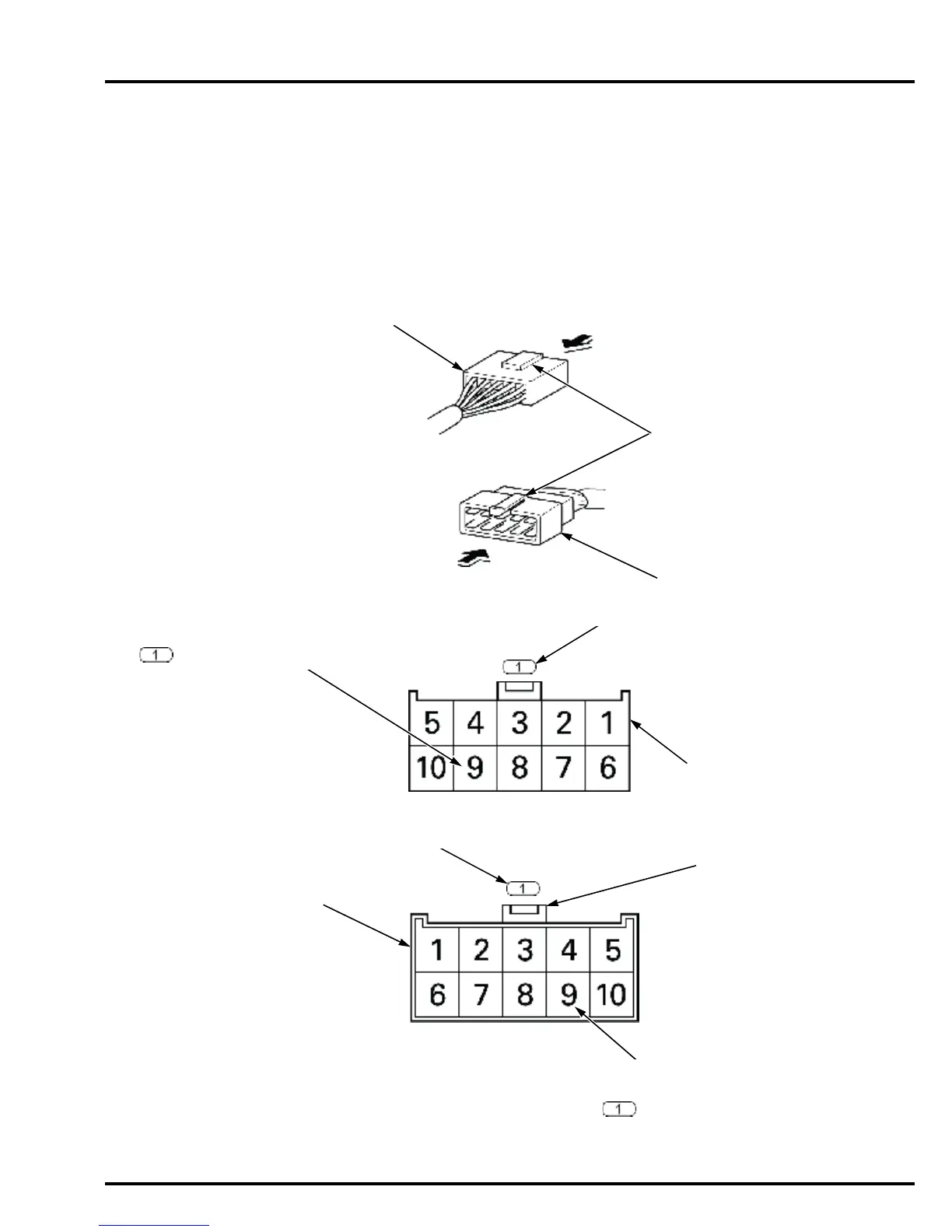
HOW TO READ CONNECTOR DRAWINGS
Connector drawings show the terminal arrangement, terminal No., number of pins, and the shape of terminal (male or female).
Both the male and female connectors are shown for the common connectors, while only the main wire harness side connectors are
shown for the dedicated connectors.
The double frame connectors represent the male connectors and the single frame connectors represent the female connectors.
Both the male and female connectors are shown by viewing them from the terminal side.
FEMALE CONNECTOR
MALE CONNECTOR
LOCK
VIEWING DIRECTION
VIEWING DIRECTION
FEMALE CONNECTOR DRAWING
(SINGLE FRAME)
Female connector viewed from the
terminal side.
MALE CONNECTOR DRAWING
(DOUBLE FRAME)
Male connector viewed from the
terminal side.
LOCK
CONNECTOR No.
CONNECTOR No.
TERMINAL No.
The system drawing shows the No.9 terminal of
the connector.
TERMINAL ARRANGEMENT
The connector drawing shows the terminal arrangement of
the connector with the lock of the connector UP.