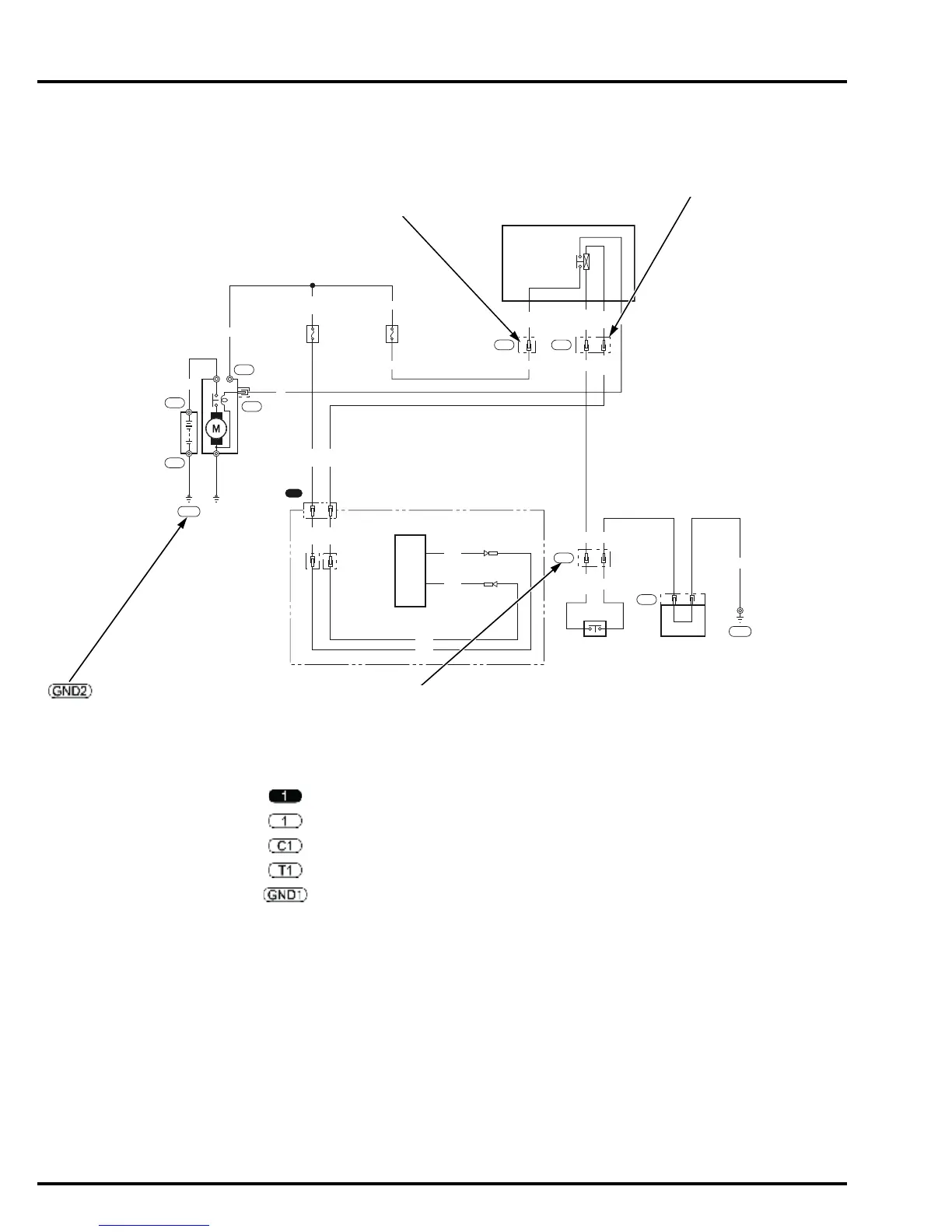
SYMBOL OF TERMINAL
It shows the shape of each terminal to identify
whether it is a male or female terminal.
TERMINAL No.
CONNECTOR/TERMINAL No.
Every connector and terminal has a number to help the users find the location and shape of
the connector and the terminal arrangement by referring to the “Connector general layout
drawing” and/or the “Connector drawing.” All the connector/terminal numbers shown in this
Service Manual are either of those shown in this section.
Indicates the ground.
(Circled GND followed with No. in
white background)
: Connector that joins a harness to a harness (Circled No. in black background)
: Connector that connects to electrical equipment (Circled No. in white background)
: Connector (Circled C followed with No. in white background)
: Terminal (Circled T followed with No. in white background)
: Ground (Circled GND followed with No. in white background)