3-13
dummyheaddummyhead
MAINTENANCE
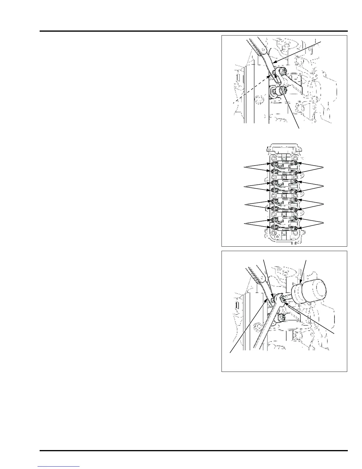
4. With the No.1 piston at top dead center of its
compression stroke as described in step 3, check
the intake and exhaust valve clearance on the No.1
cylinder by inserting a feeler gauge [1] between the
intake/exhaust side rocker arm valve adjusting
screw [2] and the valve stem end [3].
5. If adjustment is necessary, loosen the valve
adjusting lock nut [1] while holding the valve
adjusting screw [2] with a screwdriver or equivalent
tool [3].
6. Insert the feeler gauge [4] between the intake/
exhaust side rocker arm valve adjusting screw and
the valve stem end.
7. Adjust the intake and exhaust valve clearance by
turning the valve adjusting screw.
8. After adjustment, secure the valve adjusting screw,
and tighten the lock nut to the specified torque.
9. Recheck the valve clearances again. If the
measurements are out of specification, readjust the
valve clearances.
Valve clearance:
IN: 0.15 – 0.19 mm (0.006 – 0.007 in)
EX: 0.26 – 0.30 mm (0.010 – 0.012 in)
No.1
No.1
[1]
No.2
No.3
No.4
No.2
No.3
No.4
[2]
[3]
Intake side:
Exhaust side:
TORQUE:
BF90D/BF100A
Intake side:
20 N·m (2.0 kgf·m, 15 lbf·ft)
BF90D/BF100A
Exhaust side:
14 N·m (1.4 kgf·m, 10 lbf·ft)
BF75D/BF80A: 14 N·m (1.4 kgf·m, 10 lbf·ft)