Workman HDX Auto Page 4 − 57 Drive Train
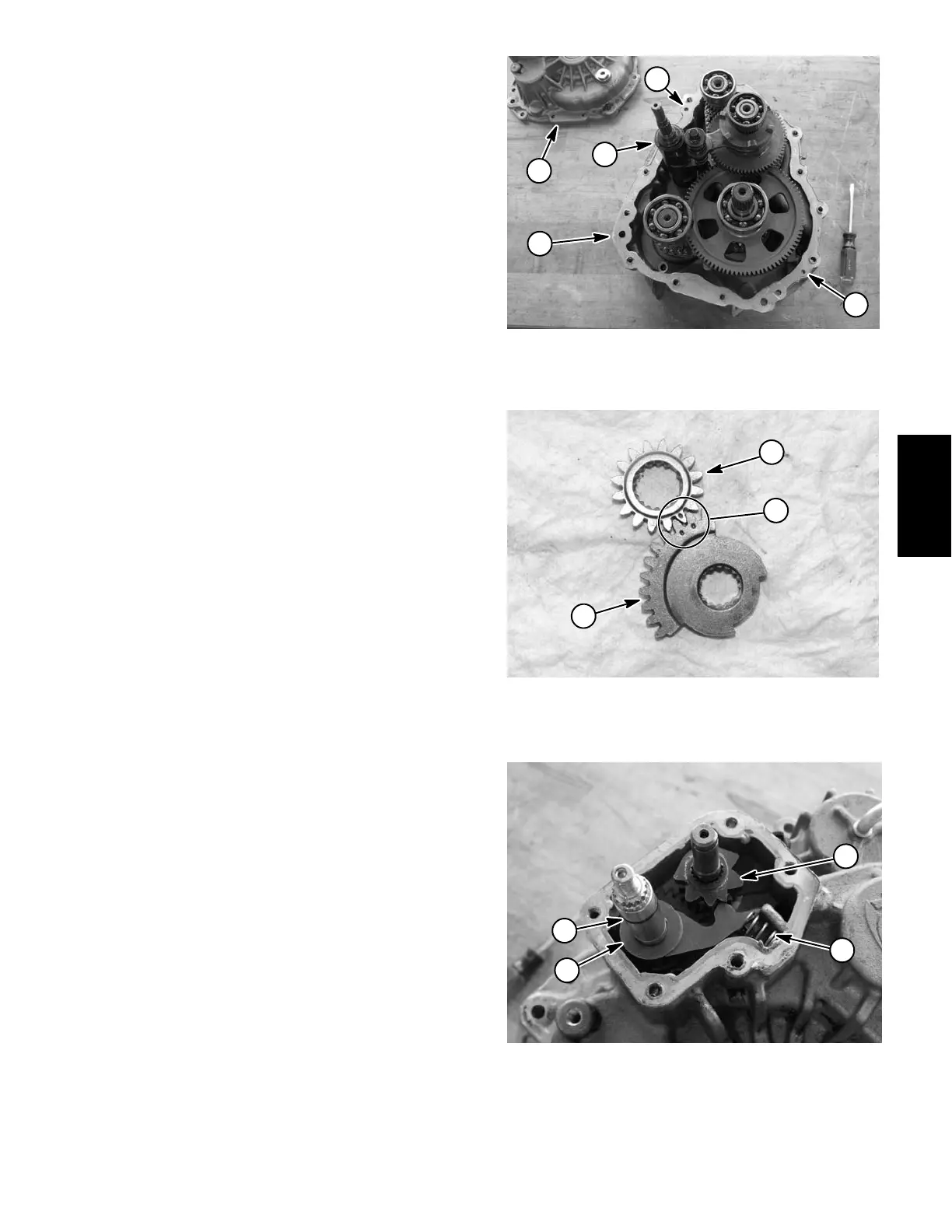
8. Carefully lower shift drum (Fig. 55 item 29) into trans-
mission while engaging the drum slots to the shift fork
pins (Fig. 67).
9. Make sure that mating surfaces of front and rear gear
case are clean. Apply silicone sealant to mating surface
of front gear case.
10.Install two (2) dowel pins (Fig. 55 item 10) into gear
case locations.
11.Carefully install rear gear case taking care to not
damage seal in gear case.
12.Secure transmission gear cases with flange head
screws. Tighten screws in three (3) steps in a crossing
pattern from 15 to 20 ft−lb (21 to 27 N−m). Make sure
that there is no shaft binding after assembly.
13. Apply a light coating of multi−purpose lithium grease
onto new O−ring (Fig. 55 item 60) for shift drum shaft. In-
stall lubricated O−ring into shaft groove.
14.Install shift components into rear gear case:
A. Noting location of missing tooth, slide sector gear
(Fig. 55 item 32) onto shift drum shaft. If necessary,
rotate shift drum so that the sector gear identification
mark is toward the location of the shift shaft (Fig. 55
item 43).
B. Noting location of missing tooth, slide sector gear
(Fig. 55 item 30) onto lower end of shift shaft. Lower
shaft with gear into rear case and align the identifica-
tion marks on the two (2) sector gears (Fig. 68).
C. Slide spacer and then detent star (Fig. 55 item 52
and 31) onto shift drum shaft. The detent star has a
missing tooth for alignment purposes.
D. Slide detent pawl (Fig. 55 item 33) onto shift shaft
making sure that recess on pawl face fully engages
the shift shaft shoulder.
E. Install compression spring (Fig. 55 item 22) into
case recess and onto the detent pawl pin.
F. Apply a light coating of multi−purpose lithium
grease onto new O−ring (Fig. 55item 51) for shift
shaft. Install lubricated O−ring into shaft groove
(Fig. 69).
15.Make sure that mating surfaces of rear gear case and
sector gear cover (Fig. 55 item 28) are clean. Apply sili-
cone sealant to mating surface of rear gear case.
16.Install sector gear cover and secure with flange head
screws. Tighten screws in two (2) steps in a crossing pat-
tern and to a final torque of 9 to 12 ft−lb (12 to 16 N−m).
1. Rear gear case
2. Front gear case
3. Dowel pin location (2)
4. Shift drum
Figure 67
2
1
3
3
4
1. Shift drum sector gear
2. Shift shaft sector gear
3. Alignment marks
Figure 68
2
1
3
Figure 69
1. Compression spring
2. Detent pawl
3. Detent star
4. O−ring
1
1
3
4
SafetyProduct Records
Drive Train